MRCSP Phase I Geologic Characterization Report - Midwest ...
MRCSP Phase I Geologic Characterization Report - Midwest ...
MRCSP Phase I Geologic Characterization Report - Midwest ...

You also want an ePaper? Increase the reach of your titles
YUMPU automatically turns print PDFs into web optimized ePapers that Google loves.
CO 2-SEQUESTRATION STORAGE CAPACITY FOR THE <strong>MRCSP</strong> PROJECT<br />
33<br />
CO 2 -SEQUESTRATION STORAGE CAPACITY FOR THE <strong>MRCSP</strong> PROJECT<br />
CO 2-STORAGE MECHANISMS IN<br />
GEOLOGIC FORMATIONS<br />
Carbon dioxide sequestration in geologic strata relies upon a<br />
number of different storage mechanisms that are based on sitespecific<br />
geologic conditions. Based on the geologic sequestration<br />
research conducted over the last decade by a number of researchers,<br />
these mechanisms are now fairly well described in published<br />
papers and proceedings of conferences such as the Greenhouse<br />
Gas Control Technology (GHGT) series organized by the International<br />
Energy Agency Greenhouse Gas R&D Programme (see<br />
www.ieagreen.org.uk for conference proceedings information) or<br />
in the Special <strong>Report</strong> on Carbon Dioxide Capture and Storage prepared<br />
by the Intergovernmental Panel on Climate Change (IPCC)<br />
(e.g. Houghton and others, 1996; 2001). The commonly discussed<br />
storage mechanisms are volumetric storage, solubility storage,<br />
adsorption storage, and mineral storage. Volumetric storage refers<br />
to the amount of CO 2 that is retained in the pore space of a geologic<br />
unit, generally as a supercritical phase retained by structural<br />
or stratigraphic traps or by the overlying cap-rock layers. Solubility<br />
storage involves dissolution of a part or all of the CO 2 into the<br />
formation waters of the geologic unit. Adsorption storage involves<br />
the holding of CO 2 molecules onto the fracture faces and into the<br />
matrix of organic-rich rock units, such as coal or black shale. Mineral<br />
storage involves the chemical reaction of CO 2 with the minerals<br />
and brine in the geologic unit. Under appropriate conditions, some<br />
chemical reactions may form a solid precipitate, permanently binding<br />
the carbon to the geologic unit. Mineral storage is not investigated<br />
as part of this report because the complex nature of the reactions<br />
and the uncertainty in reaction rates makes it difficult to determine<br />
the storage volumes on a regional scale. In addition to the types of<br />
formations and storage mechanisms evaluated in this report, basalt<br />
layers and salt caverns are also potential repositories for CO 2-storage;<br />
however, due to the early state of research for these options,<br />
they were not evaluated at this time for <strong>MRCSP</strong> region.<br />
CO 2 PROPERTIES<br />
Before the description of the calculation methods used for CO 2-<br />
storage capacity determinations can begin, it is important to briefly<br />
review the physical properties of CO 2, since these physical properties<br />
affect how much CO 2 can be placed into storage. The phase behavior<br />
of CO 2 is well understood and can be found in general chemical<br />
references such as Lemmon and others (2003) or in literature on enhanced<br />
oil recovery (e.g., Jarrell and others, 2002). Carbon dioxide<br />
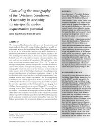
can exist as four different phases (Figure 21), as a solid, liquid, gas,<br />
or as a super-critical gas. The triple point for solid, liquid, and gas<br />
is at -69.826º F (-56.57º C) and 75.2020672 psia (0.5185 MPa). At<br />
temperatures greater than 87.8º F (31.1º C) and pressures greater than<br />
1,071 psia (7.38 MPa), CO 2 is in a super-critical state, behaving similar<br />
to a gas by filling all available space, while having the density of a<br />
liquid. Using typical parameters for the <strong>MRCSP</strong> area, such as a geothermal<br />
gradient of 0.01º F/ft (0.0182º C/m), a surface temperature of<br />
56º F (13.33º C), and a pressure gradient of 0.433 psia/ft (9,792.112<br />
Pa/m), a line representing the typical pressures and temperatures with<br />
depth can be superimposed on the phase diagram (Figure 21). This<br />
line shows that at shallow depths (less than ~2,500 ft), CO 2 would be<br />
stored in a gaseous phase, while at deeper depths (greater than ~2,500<br />
ft), most of the CO 2 will be in the super-critical gas phase, with some<br />
storage as a liquid. The recognition of the super-critical gas phase is<br />
important since, under most geologic storage scenarios being evaluated,<br />
CO 2-storage will occur as a super-critical gas.<br />
<br />
<br />
<br />
<br />
<br />
<br />
<br />
<br />
<br />
<br />
<br />
<br />
<br />
<br />
<br />
<br />
<br />
<br />
<br />
<br />
<br />
<br />
<br />
<br />
<br />
<br />
<br />
<br />
<br />
<br />
<br />
<br />
<br />
<br />
<br />
<br />
<br />
<br />
<br />
<br />
<br />
<br />
<br />
<br />
<br />
<br />
Figure 21.—CO 2 phase diagram. The triple point for CO 2 occurs at -69.826°F (-56.57°C)<br />
and 75.202 psia (0.518 MPa) (Lemmon and others, 2003). The super-critical gas phase<br />
occurs at 87.8°F (31.1°C) and 1,071 psia (7.38 MPa). The dashed line represents typical<br />
reservoir conditions in the <strong>MRCSP</strong> area.