

Physical Principles of Electron Microscopy: An Introduction to TEM ...
Physical Principles of Electron Microscopy: An Introduction to TEM ...
Physical Principles of Electron Microscopy: An Introduction to TEM ...

You also want an ePaper? Increase the reach of your titles
YUMPU automatically turns print PDFs into web optimized ePapers that Google loves.
<strong>TEM</strong> Specimens and Images 109<br />
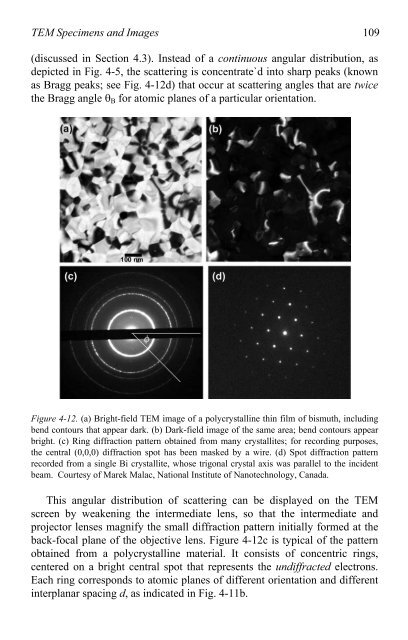
(discussed in Section 4.3). Instead <strong>of</strong> a continuous angular distribution, as<br />
depicted in Fig. 4-5, the scattering is concentrate`d in<strong>to</strong> sharp peaks (known<br />
as Bragg peaks; see Fig. 4-12d) that occur at scattering angles that are twice<br />
the Bragg angle �B for a<strong>to</strong>mic planes <strong>of</strong> a particular orientation.<br />
Figure 4-12. (a) Bright-field <strong>TEM</strong> image <strong>of</strong> a polycrystalline thin film <strong>of</strong> bismuth, including<br />
bend con<strong>to</strong>urs that appear dark. (b) Dark-field image <strong>of</strong> the same area; bend con<strong>to</strong>urs appear<br />
bright. (c) Ring diffraction pattern obtained from many crystallites; for recording purposes,<br />
the central (0,0,0) diffraction spot has been masked by a wire. (d) Spot diffraction pattern<br />
recorded from a single Bi crystallite, whose trigonal crystal axis was parallel <strong>to</strong> the incident<br />
beam. Courtesy <strong>of</strong> Marek Malac, National Institute <strong>of</strong> Nanotechnology, Canada.<br />
This angular distribution <strong>of</strong> scattering can be displayed on the <strong>TEM</strong><br />
screen by weakening the intermediate lens, so that the intermediate and<br />
projec<strong>to</strong>r lenses magnify the small diffraction pattern initially formed at the<br />
back-focal plane <strong>of</strong> the objective lens. Figure 4-12c is typical <strong>of</strong> the pattern<br />
obtained from a polycrystalline material. It consists <strong>of</strong> concentric rings,<br />
centered on a bright central spot that represents the undiffracted electrons.<br />
Each ring corresponds <strong>to</strong> a<strong>to</strong>mic planes <strong>of</strong> different orientation and different<br />
interplanar spacing d, as indicated in Fig. 4-11b.

