- Page 2 and 3: Physical Principles of Electron Mic
- Page 4 and 5: Ray F. Egerton Department of Physic
- Page 6 and 7: Contents Preface xi 1. An Introduct
- Page 8 and 9: Contents ix 7. Recent Developments
- Page 10 and 11: xii Preface textbooks, such as Will
- Page 12 and 13: 2 1.1 Limitations of the Human Eye
- Page 14 and 15: 4 Chapter 1 parallel beam of light
- Page 16 and 17: 6 Chapter 1 Figure 1-3. One of the
- Page 18 and 19: 8 Chapter 1 Figure 1-5. Light-micro
- Page 20 and 21: 10 Chapter 1 Figure 1-7. Scanning t
- Page 22 and 23: 12 Chapter 1 Figure 1-8. Early phot
- Page 24 and 25: 14 Chapter 1 Figure 1-10. JEOL tran
- Page 26 and 27: 16 Chapter 1 hydrated. But high-ene
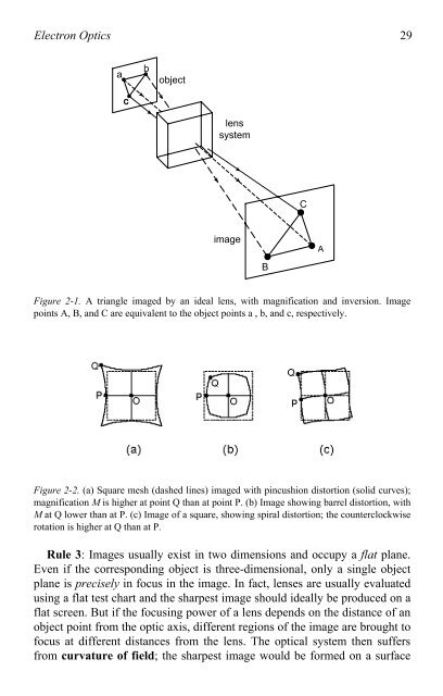
- Page 28 and 29: 18 Chapter 1 Figure 1-14. Scanning
- Page 30 and 31: 20 Chapter 1 Figure 1-16. Photograp
- Page 32 and 33: 22 Chapter 1 visible-light photons
- Page 34 and 35: 24 Chapter 1 Typically, the STM hea
- Page 36 and 37: Chapter 2 ELECTRON OPTICS Chapter 1
- Page 40 and 41: Electron Optics 31 � a n 2 ~1.5
- Page 42 and 43: Electron Optics 33 We can define im
- Page 44 and 45: Electron Optics 35 electron source
- Page 46 and 47: Electron Optics 37 symmetry and use
- Page 48 and 49: Electron Optics 39 As we said earli
- Page 50 and 51: Electron Optics 41 2.4 Focusing Pro
- Page 52 and 53: Electron Optics 43 � = [e/(8mE0)
- Page 54 and 55: Electron Optics 45 image plane. Whe
- Page 56 and 57: Electron Optics 47 procedure that i
- Page 58 and 59: Electron Optics 49 The basic physic
- Page 60 and 61: Electron Optics 51 From Eq. (2.7),
- Page 62 and 63: Electron Optics 53 y +V 1 +V 2 -V 2
- Page 64 and 65: Electron Optics 55 point from the o
- Page 66 and 67: 58 Chapter 3 3.1 The Electron Gun T
- Page 68 and 69: 60 Chapter 3 The rate of electron e
- Page 70 and 71: 62 Chapter 3 electron emission curr
- Page 72 and 73: 64 Chapter 3 As seen from the right
- Page 74 and 75: 66 Chapter 3 � r r s r � (a) (b
- Page 76 and 77: 68 Chapter 3 Table 3-2. Speed v and
- Page 78 and 79: 70 Chapter 3 where G is a large amp
- Page 80 and 81: 72 Chapter 3 The second condenser (
- Page 82 and 83: 74 Chapter 3 Figure 3-9 summarizes
- Page 84 and 85: 76 Chapter 3 resolution (especially
- Page 86 and 87: 78 Chapter 3 The major advantage of
- Page 88 and 89:
80 Chapter 3 contrast (for a given
- Page 90 and 91:
82 Chapter 3 A more correct procedu
- Page 92 and 93:
84 Chapter 3 diffraction pattern (s
- Page 94 and 95:
86 Chapter 3 Nowadays, photographic
- Page 96 and 97:
88 Chapter 3 A related concept is d
- Page 98 and 99:
90 Chapter 3 molecules, imparting a
- Page 100 and 101:
92 Chapter 3 Frequently, liquid nit
- Page 102 and 103:
94 Chapter 4 -e -e -e -e +Ze Figure
- Page 104 and 105:
96 Chapter 4 � (a) elastic z x m
- Page 106 and 107:
98 Chapter 4 � b a (a) (b) Figure
- Page 108 and 109:
100 Chapter 4 fraction of electrons
- Page 110 and 111:
102 Chapter 4 whose composition or
- Page 112 and 113:
104 Chapter 4 replica crystallites
- Page 114 and 115:
106 Chapter 4 4.5 Diffraction Contr
- Page 116 and 117:
108 Chapter 4 remain undiffracted (
- Page 118 and 119:
110 Chapter 4 Close examination of
- Page 120 and 121:
112 Chapter 4 Unfortunately, the va
- Page 122 and 123:
114 Chapter 4 Crystals can also con
- Page 124 and 125:
116 Chapter 4 A simple example of p
- Page 126 and 127:
118 Chapter 4 High-magnification ph
- Page 128 and 129:
120 Chapter 4 At this stage it is c
- Page 130 and 131:
122 Chapter 4 All of the above meth
- Page 132 and 133:
124 Chapter 4 The procedures outlin
- Page 134 and 135:
126 Chapter 5 specimen scan coils o
- Page 136 and 137:
128 Chapter 5 functions with m and
- Page 138 and 139:
130 Chapter 5 inelastic collisions
- Page 140 and 141:
132 Chapter 5 Figure 5-5. Dependenc
- Page 142 and 143:
134 Chapter 5 Figure 5-7. (a) Secon
- Page 144 and 145:
136 Chapter 5 Because each secondar
- Page 146 and 147:
138 Chapter 5 Backscattered electro
- Page 148 and 149:
140 Chapter 5 Whereas Ip remains co
- Page 150 and 151:
142 Chapter 5 Figure 5-14. Red, gre
- Page 152 and 153:
144 Chapter 5 the SE2 and SE3 compo
- Page 154 and 155:
146 Chapter 5 just-observable loss
- Page 156 and 157:
148 Chapter 5 Section 4-10. Films o
- Page 158 and 159:
150 Chapter 5 A backscattered-elect
- Page 160 and 161:
152 Chapter 5 One example of this p
- Page 162 and 163:
Chapter 6 ANALYTICAL ELECTRON MICRO
- Page 164 and 165:
Analytical Electron Microscopy 157
- Page 166 and 167:
Analytical Electron Microscopy 159
- Page 168 and 169:
Analytical Electron Microscopy 161
- Page 170 and 171:
Analytical Electron Microscopy 163
- Page 172 and 173:
Analytical Electron Microscopy 165
- Page 174 and 175:
Analytical Electron Microscopy 167
- Page 176 and 177:
Analytical Electron Microscopy 169
- Page 178 and 179:
Analytical Electron Microscopy 171
- Page 180 and 181:
Analytical Electron Microscopy 173
- Page 182 and 183:
Analytical Electron Microscopy 175
- Page 184 and 185:
178 Chapter 7 Figure 7-1. Modified
- Page 186 and 187:
180 Chapter 7 7.2 Aberration Correc
- Page 188 and 189:
182 Chapter 7 Besides decreasing th
- Page 190 and 191:
184 Chapter 7 7.4 Electron Holograp
- Page 192 and 193:
186 Chapter 7 There are now many al
- Page 194 and 195:
188 Chapter 7 holography could ther
- Page 196 and 197:
Appendix MATHEMATICAL DERIVATIONS A
- Page 198 and 199:
Mathematical Derivations 193 A.2 Im
- Page 200 and 201:
REFERENCES Binnig, G., Rohrer, H.,
- Page 202 and 203:
INDEX Aberrations, 3, 28 axial, 44
- Page 204 and 205:
Index 199 EELS, 172 Electromagnetic
- Page 206 and 207:
Index 201 Principal plane, 32, 80 P