- Page 3:
ACS800-04 Drive Modules0.55 to 200
- Page 7 and 8:
3Update Notice
- Page 9 and 10:
5Connect the optional ASTO board as
- Page 11 and 12:
7NEW (page 109): ASTO-11CNominal in
- Page 13 and 14:
5Safety instructionsWhat this chapt
- Page 15 and 16:
7GroundingThese instructions are in
- Page 17 and 18:
9OperationThese warnings are intend
- Page 19 and 20:
11Table of contentsACS800 Single Dr
- Page 21 and 22:
13Motor cable shield . . . . . . .
- Page 23 and 24:
15Altitude derating . . . . . . . .
- Page 25 and 26:
17About this manualWhat this chapte
- Page 27 and 28:
19Installation and commissioning fl
- Page 29 and 30:
21Terms and abbreviationsTerm/Abbre
- Page 31 and 32:
23ACS800-04/U4What this chapter con
- Page 33 and 34:
25Main circuit and controlDiagramTh
- Page 35 and 36:
27Planning the cabinet assemblyWhat
- Page 37 and 38:
29Cooling and degrees of protection
- Page 39 and 40:
31Inside the cabinetPrevent hot air
- Page 41 and 42:
33Control panel mounting platform k
- Page 43 and 44:
35Mechanical installationUnpacking
- Page 45 and 46:
37Installation procedure1. Mark the
- Page 47 and 48:
39R6 flange mounting12Lifting lugMo
- Page 49 and 50:
41Planning the electrical installat
- Page 51 and 52:
43Requirements tableThe following t
- Page 53 and 54:
45Note 1: The abbreviations used in
- Page 55 and 56:
47EEA / EuropeIf the drive is used
- Page 57 and 58:
492) Circuit breakers which have be
- Page 59 and 60:
51Selecting the power cablesGeneral
- Page 61 and 62:
53Additional US requirementsType MC
- Page 63 and 64:
55Before opening a contactor (DTC c
- Page 65 and 66:
57Connection of a motor temperature
- Page 67 and 68:
59Electrical installationWhat this
- Page 69 and 70:
61Power cable connectionPower cable
- Page 71 and 72:
63Frame sizes R2 to R4U1 V1 W1 UDC+
- Page 73 and 74:
65Frame size R6: Cable terminal ins
- Page 75 and 76:
67Connecting the control cablesConn
- Page 77 and 78:
69360 degrees groundingInsulation12
- Page 79 and 80:
71Installation of optional modules
- Page 81 and 82:
7356 7RMIO boardRMIO board1 2 3 1 2
- Page 83 and 84:
75Note: Location of the X41 termina
- Page 85 and 86: 77Motor control and I/O board (RMIO
- Page 87 and 88: 79External control connections (US)
- Page 89 and 90: 81Relay outputsSwitching capacityMi
- Page 91 and 92: 83Installation checklistChecklistCh
- Page 93 and 94: 85MaintenanceWhat this chapter cont
- Page 95 and 96: 87Fan replacement (R4)1. Loosen the
- Page 97 and 98: 89Fan replacement (R6)To remove the
- Page 99 and 100: 91Technical dataWhat this chapter c
- Page 101 and 102: 93ACS800-04 sizeAA kWThree-phase su
- Page 103 and 104: 95FusesgG and aR fuses for protecti
- Page 105 and 106: 97Calculation exampleDrive:• ACS8
- Page 107 and 108: 99ACS800-04 sizeUltrarapid (aR) fus
- Page 109 and 110: 101The following parameters can eff
- Page 111 and 112: 103NEMA dataRatingsThe NEMA ratings
- Page 113 and 114: 105FusesUL class T fuses for branch
- Page 115 and 116: 107Cable entriesBrake resistor, inp
- Page 117 and 118: 109AGPS-11CNominal input voltage 11
- Page 119 and 120: 111CE markingA CE mark is attached
- Page 121 and 122: 113“C-tick” marking“C-tick”
- Page 123 and 124: 115UL/CSA markingsULThe ACS800-04 a
- Page 125 and 126: 117Dimensional drawingsWhat this ch
- Page 127 and 128: 119Frame size R3 (with optional con
- Page 129 and 130: 121Frame size R5 (with optional con
- Page 131 and 132: 123Flange mounting kitsFlange mount
- Page 133 and 134: 125Flange mounting kit for frame si
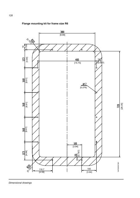
- Page 135: 127Flange mounting kit for frame si
- Page 139 and 140: 131Resistor brakingWhat this chapte
- Page 141 and 142: 133ACS800-04 typeACS800-U4 typeBrak
- Page 143 and 144: 135Protection of frame sizes R2 to
- Page 146: 3AFE68372984 Rev E ENEFFECTIVE: 31.