en/ACS800-04/U4 Hardware Manuals - VAE ProSys sro
en/ACS800-04/U4 Hardware Manuals - VAE ProSys sro
en/ACS800-04/U4 Hardware Manuals - VAE ProSys sro

Create successful ePaper yourself
Turn your PDF publications into a flip-book with our unique Google optimized e-Paper software.
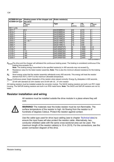
134<strong>ACS800</strong>-<strong>04</strong> type<strong>ACS800</strong>-<strong>U4</strong> typeBraking power of the chopper andthe driveP brcont(kW)690 V units-0011-7 8.0 SACE08RE44 44 210 1-0016-7 11 SACE08RE44 44 210 1-0020-7 16 SACE08RE44 44 210 1-0025-7 20 SACE08RE44 44 210 1-0030-7 28 SACE15RE22 22 420 2-0<strong>04</strong>0-7 22 / 33 1) SACE15RE22 22 420 2-0050-7 45 SACE15RE13 13 435 2-0060-7 56 SACE15RE13 13 435 2-0070-7 68 SAFUR90F575 8 1800 4.5-0100-7 83 SAFUR90F575 8 1800 4.5-0120-7 113 SAFUR80F500 6 2400 6-0145-7 160 SAFUR80F500 6 2400 6-0175-7 160 SAFUR80F500 6 2400 6-0205-7 160 SAFUR80F500 6 2400 6PDM code 00096931-JP brcont The drive and the chopper will withstand this continuous braking power. The braking is considered continuous if thebraking time exceeds 30 s.Note: The braking <strong>en</strong>ergy transmitted to the specified resistor(s) in 400 seconds may not exceed E R .R Resistance value for the listed resistor assembly. Note: This is also the minimum allowed resistance for the brakingresistor.E R Short <strong>en</strong>ergy pulse that the resistor assembly withstands every 400 seconds. This <strong>en</strong>ergy will heat the resistorelem<strong>en</strong>t from 40°C (1<strong>04</strong>°F) to the maximum allowable temperature.P Rcont Continuous power (heat) dissipation of the resistor wh<strong>en</strong> placed correctly. Energy E R dissipates in 400 seconds.1)22 kW with standard 22 ohm resistor and 33 kW with 32…37 ohm resistorAll braking resistors must be installed outside the converter module. The SACE braking resistors are built in an IP21 metalhousing. The SAFUR braking resistors are built in an IP00 metal frame. Note: The SACE and SAFUR resistors are not ULlisted.Resistor installation and wiringBrake resistor(s)TypeR(ohm)All resistors must be installed outside the drive module in a place where they willcool.E R(kJ)P Rcont(kW)WARNING! The materials near the brake resistor must be non-flammable. Thesurface temperature of the resistor is high. Air flowing from the resistor is ofhundreds of degrees Celsius. Protect the resistor against contact.Use the cable type used for drive input cabling (see to chapter Technical data) to<strong>en</strong>sure the input fuses will also protect the resistor cable. Alternatively, twoconductorshielded cable with the same cross-sectional area can be used. Themaximum l<strong>en</strong>gth of the resistor cable(s) is 10 m (33 ft). For the connections, see thepower connection diagram of the drive.Resistor braking