en/ACS800-04/U4 Hardware Manuals - VAE ProSys sro
en/ACS800-04/U4 Hardware Manuals - VAE ProSys sro
en/ACS800-04/U4 Hardware Manuals - VAE ProSys sro

You also want an ePaper? Increase the reach of your titles
YUMPU automatically turns print PDFs into web optimized ePapers that Google loves.
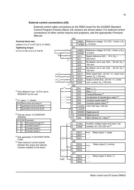
79External control connections (US)External control cable connections to the RMIO board for the <strong>ACS800</strong> StandardControl Program (Factory Macro US version) are shown below. For external controlconnections of other control macros and programs, see the appropriate FirmwareManual.X20Terminal block size:1 VREF- Refer<strong>en</strong>ce voltage -10 V DC, 1 kohm < R Lcables 0.3 to 3.3 mm 2 (22 to 12 AWG)2 AGND < 10 kohmTight<strong>en</strong>ing torque:0.2 to 0.4 Nm (0.2 to 0.3 lbf ft)X211 VREF+ Refer<strong>en</strong>ce voltage 10 V DC, 1 kohm < R L 4 AI1- 200 kohm5 AI2+ By default, not in use. 0(4) ... 20 mA, R in =6 AI2- 100 ohm7 AI3+ By default, not in use. 0(4) ... 20 mA, R in =8 AI3- 100 ohmrpm9 AO1+ Motor speed 0(4)...20 mA = 0...motor nom.10 AO1- speed, R L < 700 ohmA11 AO2+ Output curr<strong>en</strong>t 0(4)...20 mA = 0...motor12 AO2- nom. curr<strong>en</strong>t, R L < 700 ohmX221 DI1 Start ( )1) Only effective if par. 10.03 is set to2 DI2 Stop ( )REQUEST by the user.3 DI3 Forward/Reverse 1)4 DI4 Acceleration & deceleration select 2)2) 0 = op<strong>en</strong>, 1 = closed5 DI5 Constant speed select 3)DI4 Ramp times according to6 DI6 Constant speed select 3)0 parameters 22.02 and 22.037 +24VD +24 V DC max. 100 mA1 parameters 22.<strong>04</strong> and 22.058 +24VD9 DGND1 Digital ground3) See par. group 12 CONSTANT10 DGND2 Digital groundSPEEDS.11 DIIL Start interlock (0 = stop) 4)DI5 DI6 OperationX230 0 Set speed through AI11 +24V Auxiliary voltage output and input, nonisolated,24 V DC 250 mA 5)1 0 Constant speed 12 GND0 1 Constant speed 2X251 1 Constant speed 31 RO1 Relay output 1: ready4) 2 RO1See parameter 21.09 START INTRL3 RO1FUNC.5) X26Total maximum curr<strong>en</strong>t sharedbetwe<strong>en</strong> this output and optional1 RO2 Relay output 2: runningmodules installed on the board.2 RO23 RO2X271 RO3 Relay output 3: fault (-1)Fault 2 RO33 RO3Motor control and I/O board (RMIO)