en/ACS800-04/U4 Hardware Manuals - VAE ProSys sro
en/ACS800-04/U4 Hardware Manuals - VAE ProSys sro
en/ACS800-04/U4 Hardware Manuals - VAE ProSys sro

Create successful ePaper yourself
Turn your PDF publications into a flip-book with our unique Google optimized e-Paper software.
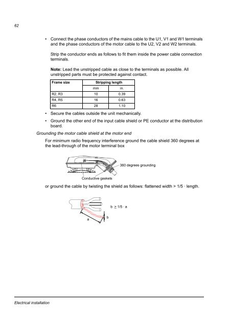
62• Connect the phase conductors of the mains cable to the U1, V1 and W1 terminalsand the phase conductors of the motor cable to the U2, V2 and W2 terminals.Strip the conductor <strong>en</strong>ds as follows to fit them inside the power cable connectionterminals.Note: Lead the unstripped cable as close to the terminals as possible. Allunstripped parts must be protected against contact.Frame sizeStripping l<strong>en</strong>gthmmin.R2, R3 10 0.39R4, R5 16 0.63R6 28 1.10• Secure the cables outside the unit mechanically.• Ground the other <strong>en</strong>d of the input cable shield or PE conductor at the distributionboard.Grounding the motor cable shield at the motor <strong>en</strong>dFor minimum radio frequ<strong>en</strong>cy interfer<strong>en</strong>ce ground the cable shield 360 degrees atthe lead-through of the motor terminal box360 degrees groundingConductive gasketsor ground the cable by twisting the shield as follows: flatt<strong>en</strong>ed width > 1/5 · l<strong>en</strong>gth.b > 1/5 · aabElectrical installation