- Page 1: GBG4 Multi ChannelWeighing Instrume
- Page 4 and 5: Technical ManualPRECAUTIONSREAD thi
- Page 6 and 7: Technical ManualFunctionsMeasuremen
- Page 8 and 9: Technical ManualTechnical dataEnclo
- Page 10 and 11: Technical ManualCPUModule typeCPU m
- Page 14 and 15: Technical ManualDeviceNetModule typ
- Page 16 and 17: Technical ManualOrdering informatio
- Page 18 and 19: Technical Manual1-14
- Page 20 and 21: Technical Manual!Electrical install
- Page 22 and 23: Technical ManualField BusSlot for o
- Page 24 and 25: Technical ManualAC SUPPLY - 110-240
- Page 26 and 27: Technical Manual4-wire connectionTr
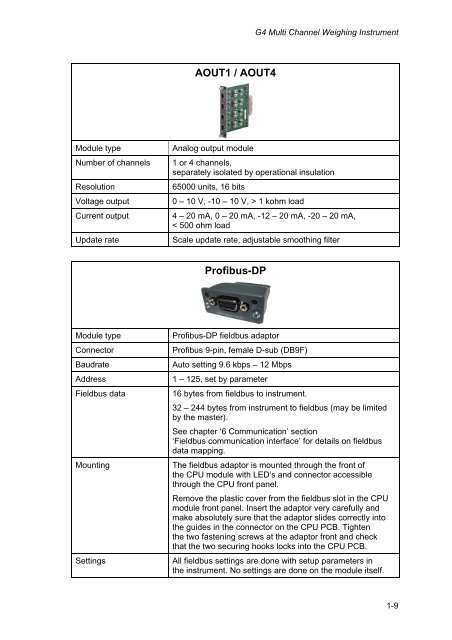
- Page 28 and 29: Technical ManualAOUT1 and AOUT4!The
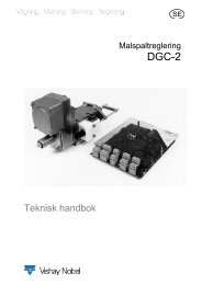
- Page 30 and 31: Technical ManualProfibus-DP Fieldbu
- Page 32 and 33: Technical ManualDeviceNet Fieldbus
- Page 34 and 35: Technical ManualFront panelDisplayA
- Page 36 and 37: Technical Manual2-18
- Page 38 and 39: Technical Manualrate and data forma
- Page 40 and 41: Technical ManualWhen editing a choi
- Page 42 and 43: Technical ManualMenu structureMain
- Page 44 and 45: Technical ManualParametersOn the fo
- Page 46 and 47: Technical ManualRange/AlternativesD
- Page 48 and 49: Technical ManualRange/Alternatives
- Page 50 and 51: Technical ManualRange/AlternativesE
- Page 52 and 53: Technical ManualRange/Alternatives1
- Page 54 and 55: Technical ManualRange/Alternatives1
- Page 56 and 57: Technical ManualRange/AlternativesE
- Page 58 and 59: Technical ManualRange/AlternativesE
- Page 60 and 61: Technical ManualRange/AlternativesE
- Page 62 and 63:
Technical ManualRange/AlternativesM
- Page 64 and 65:
Technical ManualRange/AlternativesE
- Page 66 and 67:
Technical ManualRange/AlternativesD
- Page 68 and 69:
Technical ManualRange/AlternativesE
- Page 70 and 71:
Technical ManualRange/AlternativesE
- Page 72 and 73:
Technical ManualRange/AlternativesE
- Page 74 and 75:
Technical ManualRange/AlternativesE
- Page 76 and 77:
Technical ManualIf the weight indic
- Page 78 and 79:
Technical ManualData sheet calibrat
- Page 80 and 81:
Technical Manualfor the selected nu
- Page 82 and 83:
Technical ManualDisplay alternative
- Page 84 and 85:
Technical ManualSecurity locksIn th
- Page 86 and 87:
Technical ManualGross/Net operation
- Page 88 and 89:
Technical ManualMain menuTo reach t
- Page 90 and 91:
Technical ManualLevel supervisionTh
- Page 92 and 93:
Technical ManualUse of inputs and o
- Page 94 and 95:
Technical ManualFlow rateGeneralThe
- Page 96 and 97:
Technical ManualFlow rate update ti
- Page 98 and 99:
Technical Manual5-18
- Page 100 and 101:
Technical ManualSetup of Modbus RTU
- Page 102 and 103:
Technical ManualGeneral registersTh
- Page 104 and 105:
Technical ManualData type:IntegerDa
- Page 107 and 108:
G4 Multi Channel Weighing Instrumen
- Page 109 and 110:
G4 Multi Channel Weighing Instrumen
- Page 111 and 112:
G4 Multi Channel Weighing Instrumen
- Page 113 and 114:
G4 Multi Channel Weighing Instrumen
- Page 115 and 116:
G4 Multi Channel Weighing Instrumen
- Page 117 and 118:
G4 Multi Channel Weighing Instrumen
- Page 119 and 120:
G4 Multi Channel Weighing Instrumen
- Page 121 and 122:
G4 Multi Channel Weighing Instrumen
- Page 123 and 124:
G4 Multi Channel Weighing Instrumen
- Page 125 and 126:
G4 Multi Channel Weighing Instrumen
- Page 127 and 128:
G4 Multi Channel Weighing Instrumen
- Page 129 and 130:
G4 Multi Channel Weighing Instrumen
- Page 131 and 132:
G4 Multi Channel Weighing Instrumen
- Page 133 and 134:
G4 Multi Channel Weighing Instrumen
- Page 135 and 136:
G4 Multi Channel Weighing Instrumen
- Page 137 and 138:
G4 Multi Channel Weighing Instrumen
- Page 139 and 140:
G4 Multi Channel Weighing Instrumen
- Page 141 and 142:
G4 Multi Channel Weighing Instrumen
- Page 143 and 144:
G4 Multi Channel Weighing Instrumen
- Page 145 and 146:
G4 Multi Channel Weighing Instrumen
- Page 147 and 148:
G4 Multi Channel Weighing Instrumen
- Page 149 and 150:
G4 Multi Channel Weighing Instrumen
- Page 152:
Publication 600 852 R2© Vishay Nob