G4 Multi Channel Weighing Instrument. PM/DT/HE Technical Manual
G4 Multi Channel Weighing Instrument. PM/DT/HE Technical Manual
G4 Multi Channel Weighing Instrument. PM/DT/HE Technical Manual

You also want an ePaper? Increase the reach of your titles
YUMPU automatically turns print PDFs into web optimized ePapers that Google loves.
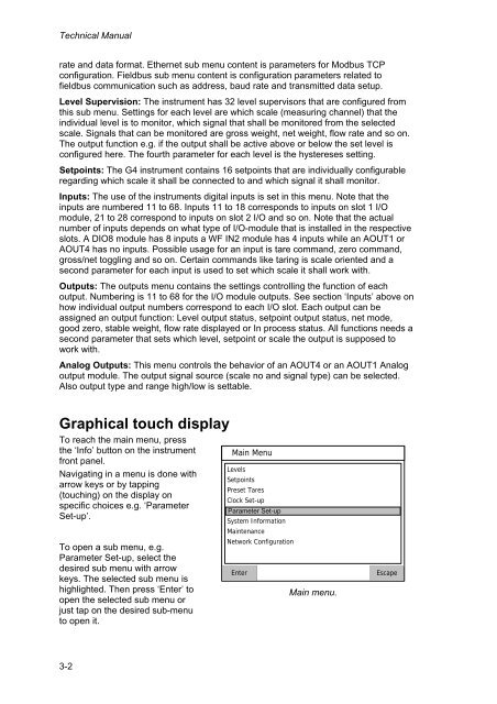
<strong>Technical</strong> <strong>Manual</strong>rate and data format. Ethernet sub menu content is parameters for Modbus TCPconfiguration. Fieldbus sub menu content is configuration parameters related tofieldbus communication such as address, baud rate and transmitted data setup.Level Supervision: The instrument has 32 level supervisors that are configured fromthis sub menu. Settings for each level are which scale (measuring channel) that theindividual level is to monitor, which signal that shall be monitored from the selectedscale. Signals that can be monitored are gross weight, net weight, flow rate and so on.The output function e.g. if the output shall be active above or below the set level isconfigured here. The fourth parameter for each level is the hystereses setting.Setpoints: The <strong>G4</strong> instrument contains 16 setpoints that are individually configurableregarding which scale it shall be connected to and which signal it shall monitor.Inputs: The use of the instruments digital inputs is set in this menu. Note that theinputs are numbered 11 to 68. Inputs 11 to 18 corresponds to inputs on slot 1 I/Omodule, 21 to 28 correspond to inputs on slot 2 I/O and so on. Note that the actualnumber of inputs depends on what type of I/O-module that is installed in the respectiveslots. A DIO8 module has 8 inputs a WF IN2 module has 4 inputs while an AOUT1 orAOUT4 has no inputs. Possible usage for an input is tare command, zero command,gross/net toggling and so on. Certain commands like taring is scale oriented and asecond parameter for each input is used to set which scale it shall work with.Outputs: The outputs menu contains the settings controlling the function of eachoutput. Numbering is 11 to 68 for the I/O module outputs. See section ‘Inputs’ above onhow individual output numbers correspond to each I/O slot. Each output can beassigned an output function: Level output status, setpoint output status, net mode,good zero, stable weight, flow rate displayed or In process status. All functions needs asecond parameter that sets which level, setpoint or scale the output is supposed towork with.Analog Outputs: This menu controls the behavior of an AOUT4 or an AOUT1 Analogoutput module. The output signal source (scale no and signal type) can be selected.Also output type and range high/low is settable.Graphical touch displayTo reach the main menu, pressthe ‘Info’ button on the instrumentfront panel.Navigating in a menu is done witharrow keys or by tapping(touching) on the display onspecific choices e.g. ‘ParameterSet-up’.To open a sub menu, e.g.Parameter Set-up, select thedesired sub menu with arrowkeys. The selected sub menu ishighlighted. Then press ‘Enter’ toopen the selected sub menu orjust tap on the desired sub-menuto open it.Main MenuLevelsSetpointsPreset TaresClock Set-upParameter Set-upSystem InformationMaintenanceNetwork ConfigurationEnterMain menu.Escape3-2