Heiss W.D. (ed.) Quantum dots.. a doorway to - tiera.ru
Heiss W.D. (ed.) Quantum dots.. a doorway to - tiera.ru
Heiss W.D. (ed.) Quantum dots.. a doorway to - tiera.ru

You also want an ePaper? Increase the reach of your titles
YUMPU automatically turns print PDFs into web optimized ePapers that Google loves.
G ( e / h)<br />
2<br />
2<br />
1<br />
0<br />
Semiconduc<strong>to</strong>r Few-Electron <strong>Quantum</strong> Dots as Spin Qubits 53<br />
a<br />
drain1 T source2<br />
Q-L<br />
source1<br />
b<br />
I DOT<br />
I QPC<br />
L M R<br />
P L<br />
-0.50 -0.55 -0.60 -0.65<br />
V Q-L (V)<br />
P R<br />
I QPC<br />
200 nm<br />
Q-R<br />
drain2<br />
I QPC (nA)<br />
I DOT (pA)<br />
QPC M<br />
dI / dV<br />
(arb. units)<br />
5<br />
4<br />
3<br />
-1.25 -1.30 -1.35 -1.40<br />
30<br />
0<br />
c<br />
d<br />
V M (V)<br />
transport<br />
QPC<br />
-1.25 -1.30 -1.35 -1.40<br />
V M (V)<br />
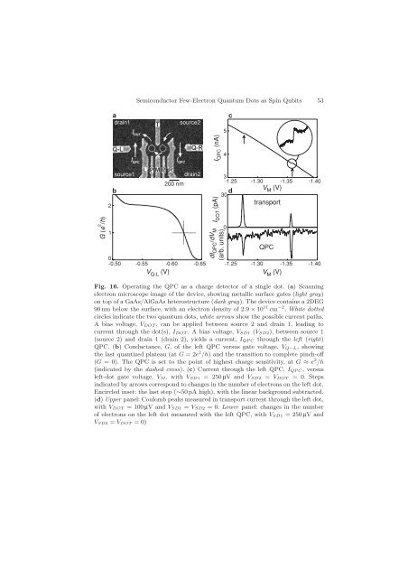
Fig. 16. Operating the QPC as a charge detec<strong>to</strong>r of a single dot. (a) Scanning<br />
electron microscope image of the device, showing metallic surface gates (light gray)<br />
on <strong>to</strong>p of a GaAs/AlGaAs heterost<strong>ru</strong>cture (dark gray). The device contains a 2DEG<br />
90 nm below the surface, with an electron density of 2.9 × 10 11 cm −2 . White dott<strong>ed</strong><br />
circles indicate the two quantum <strong>dots</strong>, white arrows show the possible current paths.<br />
A bias voltage, VDOT , can be appli<strong>ed</strong> between source 2 and drain 1, leading <strong>to</strong><br />
current through the dot(s), IDOT .Abiasvoltage,VSD1 (VSD2), between source 1<br />
(source 2) and drain 1 (drain 2), yields a current, IQP C through the left (right)<br />
QPC. (b) Conductance, G, of the left QPC versus gate voltage, VQ−L, showing<br />
the last quantiz<strong>ed</strong> plateau (at G =2e 2 /h) and the transition <strong>to</strong> complete pinch-off<br />
(G = 0). The QPC is set <strong>to</strong> the point of highest charge sensitivity, at G ≈ e 2 /h<br />
(indicat<strong>ed</strong> by the dash<strong>ed</strong> cross). (c) Current through the left QPC, IQP C, versus<br />
left-dot gate voltage, VM , with VSD1 = 250µV and VSD2 = VDOT = 0. Steps<br />
indicat<strong>ed</strong> by arrows correspond <strong>to</strong> changes in the number of electrons on the left dot.<br />
Encircl<strong>ed</strong> inset: the last step (∼50 pA high), with the linear background subtract<strong>ed</strong>.<br />
(d) Upper panel: Coulomb peaks measur<strong>ed</strong> in transport current through the left dot,<br />
with VDOT = 100 µV andVSD1 = VSD2 =0.Lower panel: changes in the number<br />
of electrons on the left dot measur<strong>ed</strong> with the left QPC, with VSD1 =250µV and<br />
VSD2 = VDOT =0)