The Impact of Dennard's Scaling Theory - IEEE
The Impact of Dennard's Scaling Theory - IEEE
The Impact of Dennard's Scaling Theory - IEEE
- TAGS
- scaling
- www.ieee.org

You also want an ePaper? Increase the reach of your titles
YUMPU automatically turns print PDFs into web optimized ePapers that Google loves.
causes so-called random telegraph signals, which<br />
determine the low frequency noise <strong>of</strong> the transistors.<br />
<strong>The</strong> reduction effect is found to be present in all technologies<br />
investigated: from 10μm down to 0.12μm,<br />
both N and P MOSFETs and works for switching frequencies<br />
up to at least 3GHz.<br />
For large-geometry transistors we generally see a<br />
significant reduction, whereas for very small-sized<br />
modern devices the noise can decrease but also<br />
increase. This is due to the very small number <strong>of</strong><br />
traps in the transistors (sometimes only one trap)<br />
while the phenomenon depends strongly on the<br />
energy distribution <strong>of</strong> the traps. Details can be<br />
found in [4].<br />
Other known techniques to reduce the effect <strong>of</strong> LF<br />
noise in electronic circuits are chopping and correlated<br />
double sampling. <strong>The</strong> LF noise can also be<br />
reduced by increasing gate area <strong>of</strong> the MOSFETS, at<br />
the cost <strong>of</strong> area and/or power consumption. <strong>The</strong><br />
switched bias technique <strong>of</strong>fers an orthogonal method<br />
to reduce the intrinsic LF noise in the transistor itself.<br />
It is beneficial especially in circuits where switching<br />
already occurs, such as oscillators and discrete time<br />
circuits.<br />
Distortion Cancelling using Poly-Phase<br />
Technique<br />
In deep submicron technology, distortion becomes<br />
an increasing problem. Large signals are required<br />
for dynamic range reasons or simply because for a<br />
given radio standard dictates the output power to be<br />
delivered by a power amplifier. <strong>The</strong> transistors,<br />
however, have less voltage gain and exhibit very<br />
non-linear behavior, which makes linear circuit<br />
design a challenge.<br />
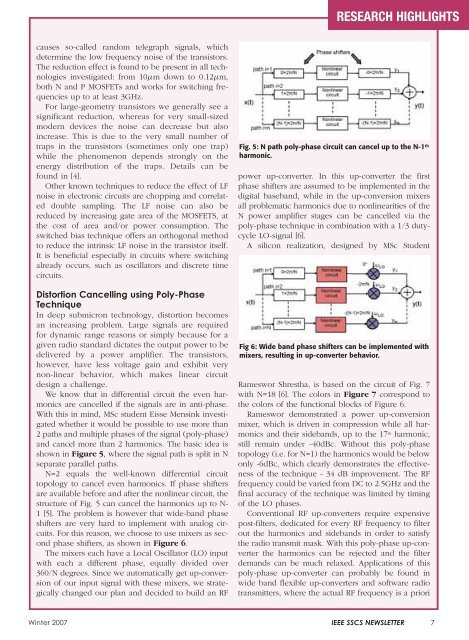
We know that in differential circuit the even harmonics<br />
are cancelled if the signals are in anti-phase.<br />
With this in mind, MSc student Eisse Mensink investigated<br />
whether it would be possible to use more than<br />
2 paths and multiple phases <strong>of</strong> the signal (poly-phase)<br />
and cancel more than 2 harmonics. <strong>The</strong> basic idea is<br />
shown in Figure 5, where the signal path is split in N<br />
separate parallel paths.<br />
N=2 equals the well-known differential circuit<br />
topology to cancel even harmonics. If phase shifters<br />
are available before and after the nonlinear circuit, the<br />
structure <strong>of</strong> Fig. 5 can cancel the harmonics up to N-<br />
1 [5]. <strong>The</strong> problem is however that wide-band phase<br />
shifters are very hard to implement with analog circuits.<br />
For this reason, we choose to use mixers as second<br />
phase shifters, as shown in Figure 6.<br />
<strong>The</strong> mixers each have a Local Oscillator (LO) input<br />
with each a different phase, equally divided over<br />
360/N degrees. Since we automatically get up-conversion<br />
<strong>of</strong> our input signal with these mixers, we strategically<br />
changed our plan and decided to build an RF<br />
RESEARCH HIGHLIGHTS<br />
Fig. 5: N path poly-phase circuit can cancel up to the N-1 th<br />
harmonic.<br />
power up-converter. In this up-converter the first<br />
phase shifters are assumed to be implemented in the<br />
digital baseband, while in the up-conversion mixers<br />
all problematic harmonics due to nonlinearities <strong>of</strong> the<br />
N power amplifier stages can be cancelled via the<br />
poly-phase technique in combination with a 1/3 dutycycle<br />
LO-signal [6].<br />
A silicon realization, designed by MSc Student<br />
Fig 6: Wide band phase shifters can be implemented with<br />
mixers, resulting in up-converter behavior.<br />
Rameswor Shrestha, is based on the circuit <strong>of</strong> Fig. 7<br />
with N=18 [6]. <strong>The</strong> colors in Figure 7 correspond to<br />
the colors <strong>of</strong> the functional blocks <strong>of</strong> Figure 6.<br />
Rameswor demonstrated a power up-conversion<br />
mixer, which is driven in compression while all harmonics<br />
and their sidebands, up to the 17 th harmonic,<br />
still remain under -40dBc. Without this poly-phase<br />
topology (i.e. for N=1) the harmonics would be below<br />
only -6dBc, which clearly demonstrates the effectiveness<br />
<strong>of</strong> the technique - 34 dB improvement. <strong>The</strong> RF<br />
frequency could be varied from DC to 2.5GHz and the<br />
final accuracy <strong>of</strong> the technique was limited by timing<br />
<strong>of</strong> the LO phases.<br />
Conventional RF up-converters require expensive<br />
post-filters, dedicated for every RF frequency to filter<br />
out the harmonics and sidebands in order to satisfy<br />
the radio transmit mask. With this poly-phase up-converter<br />
the harmonics can be rejected and the filter<br />
demands can be much relaxed. Applications <strong>of</strong> this<br />
poly-phase up-converter can probably be found in<br />
wide band flexible up-converters and s<strong>of</strong>tware radio<br />
transmitters, where the actual RF frequency is a priori<br />
Winter 2007 <strong>IEEE</strong> SSCS NEWSLETTER 7