- Page 1 and 2:
Metal Foams: A Design Guide
- Page 3 and 4:
Copyright © 2000 by Butterworth-He
- Page 5 and 6:
vi Contents 4.3 Foam property chart
- Page 7 and 8:
viii Contents 17 Case studies 217 1
- Page 9 and 10:
List of contributors M.F. Ashby Cam
- Page 11 and 12:
Table of physical constants and con
- Page 13 and 14:
Chapter 1 Introduction Metal foams
- Page 15 and 16:
Activity Research Industrial take-u
- Page 17 and 18:
Application Comment Introduction Bi
- Page 19 and 20:
Cell size (cm) Making metal foams 7
- Page 21 and 22:
Making metal foams solidify. The th
- Page 23 and 24:
Making metal foams 11 2.4 Gas-relea
- Page 25 and 26:
a) Preform Polymer ligaments d) Rem
- Page 27 and 28:
a) Vapor deposition of Nickel b) Bu
- Page 29 and 30:
Process Steps a) Powder / Can prepa
- Page 31 and 32:
Making metal foams 19 flight in a t
- Page 33 and 34:
a) Metal - Hydrogen binary phase di
- Page 35 and 36:
Entrapped gas expansion Making meta
- Page 37 and 38:
(a) (b) (c) 100µm Characterization
- Page 39 and 40:
E/E bulk σ peak /σ bulk 1.2 1.0 0
- Page 41 and 42:
Stress (MPa) Characterization metho
- Page 43 and 44:
Characterization methods 31 foam sp
- Page 45 and 46:
Characterization methods 33 ž Prop
- Page 47 and 48:
F/2 F/2 F/2 F/2 τ Core Characteriz
- Page 49 and 50:
Characterization methods 37 40 40 4
- Page 51 and 52:
Characterization methods 39 Gioux,
- Page 53 and 54:
(a) (b) (c) Properties of metal foa
- Page 55 and 56:
Table 4.1 (a) Ranges a for mechanic
- Page 57 and 58:
Stress, σ Schematic Young's modulu
- Page 59 and 60:
Properties of metal foams 47 foams.
- Page 61 and 62:
Properties of metal foams 49 show t
- Page 63 and 64:
Modulus 0.5 /Density (GPa 0.5 /(Mg/
- Page 65 and 66:
elations take the form P Ł � Ł
- Page 67 and 68:
Chapter 5 Design analysis for mater
- Page 69 and 70:
Table 5.1 Design requirements Desig
- Page 71 and 72:
Design analysis for material select
- Page 73 and 74:
5.4 Where might metal foams excel?
- Page 75 and 76:
Table 6.1 Constitutive equations fo
- Page 77 and 78:
h SECTION h o h i d d o a b ;;; QQQ
- Page 79 and 80:
6.3 Elastic deflection of beams and
- Page 81 and 82:
6.4 Failure of beams and panels (a)
- Page 83 and 84:
;; ;;; ;; M ;; ;;; ;; ;;; ;; ;; ;;
- Page 85 and 86: Torsion of shafts T T,q T T,q Yield
- Page 87 and 88: R a 2 Flow field R F R 2a 2 F F s c
- Page 89 and 90: ;; ; QQ Q ¢¢ ¢ ;; ;; QQ QQ ¢¢
- Page 91 and 92: ; ;; Creep p e p e • Area A u F 2
- Page 93 and 94: and its deviatoric (i.e. shear) com
- Page 95 and 96: Normalized effective stress 1.4 1.2
- Page 97 and 98: A constitutive model for metal foam
- Page 99 and 100: A constitutive model for metal foam
- Page 101 and 102: Stress amplitude, ∆σ + Stress,
- Page 103 and 104: Axial strain (%) 5 4 3 2 1 0 0 σma
- Page 105 and 106: Nominal compressive strain Nominal
- Page 107 and 108: σ max σ pl τ max τ pl σ max σ
- Page 109 and 110: Design for fatigue with metal foams
- Page 111 and 112: the net section stress criterion re
- Page 113 and 114: E σ pl (m) 10 1 0.1 0.01 0.1 Relat
- Page 115 and 116: Chapter 9 Design for creep with met
- Page 117 and 118: Design for creep with metal foams 1
- Page 119 and 120: instead to: � Pε 3 D Pε0 2 s Ł
- Page 121 and 122: Time to failure (hours) 10 2 10 1 1
- Page 123 and 124: Design for creep with metal foams 1
- Page 125 and 126: Chapter 10 Sandwich structures Sand
- Page 127 and 128: Sandwich structures 115 The elastic
- Page 129 and 130: Indentation Sandwich structures 117
- Page 131 and 132: H H Core shear Core shear Collapse
- Page 133 and 134: 0.5 10−1 t c t c 10 −2 0.5 10
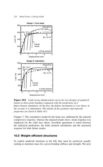
- Page 135: Sandwich structures 123 the contact
- Page 139 and 140: c t p p Figure 10.9 Sandwich panel
- Page 141 and 142: Sandwich structures 129 with k ¾ D
- Page 143 and 144: c/ Face sheet yielding 0.14 0.12 0.
- Page 145 and 146: Weight index, ψ 10 −1 10 −2 10
- Page 147 and 148: Sandwich structures 135 To construc
- Page 149 and 150: Sandwich structures 137 The associa
- Page 151 and 152: Sandwich structures 139 Note that,
- Page 153 and 154: where D � 2⊲1 Eft 2 f ⊳GcR Sa
- Page 155 and 156: Weight index ψ = W/2πR 2 ρ s W c
- Page 157 and 158: Sandwich structures 145 plastic yie
- Page 159 and 160: Sandwich structures 147 within the
- Page 161 and 162: Sandwich structures 149 Shuaeib, F.
- Page 163 and 164: Energy management: packaging and bl
- Page 165 and 166: Energy management: packaging and bl
- Page 167 and 168: Energy/Unit cost (kJ/£) 10 1 0.1 0
- Page 169 and 170: Energy management: packaging and bl
- Page 171 and 172: ys crushes axially at the load Ener
- Page 173 and 174: Energy management: packaging and bl
- Page 175 and 176: Energy management: packaging and bl
- Page 177 and 178: Energy management: packaging and bl
- Page 179 and 180: peak pressure MPa Impulse/(mass of
- Page 181 and 182: Energy management: packaging and bl
- Page 183 and 184: Chapter 12 Sound absorption and vib
- Page 185 and 186: Sound absorption and vibration supp
- Page 187 and 188:
Sound absorption and vibration supp
- Page 189 and 190:
0 Sound absorption and vibration su
- Page 191 and 192:
Sound absorption and vibration supp
- Page 193 and 194:
Chapter 13 Thermal management and h
- Page 195 and 196:
Thermal management and heat transfe
- Page 197 and 198:
Thermal management and heat transfe
- Page 199 and 200:
~ P ~ Re 2.6 1000 800 600 400 200 0
- Page 201 and 202:
Chapter 14 Electrical properties of
- Page 203 and 204:
Electrical properties of metal foam
- Page 205 and 206:
Electrical properties of metal foam
- Page 207 and 208:
15.3 Joining of metal foams Cutting
- Page 209 and 210:
Pull-out load, F p (N) 10 5 10 4 10
- Page 211 and 212:
Cyclic loading of fasteners Cutting
- Page 213 and 214:
Time, material, energy, capital, in
- Page 215 and 216:
Cost estimation and viability 203 A
- Page 217 and 218:
$/Unit Melting Schematic of the liq
- Page 219 and 220:
Performance metric, P2 B Non-domina
- Page 221 and 222:
Cost estimation and viability 209 t
- Page 223 and 224:
Cost estimation and viability 211 i
- Page 225 and 226:
P 2 = 1/Loss coefficient (−) 1000
- Page 227 and 228:
Cost estimation and viability 215 C
- Page 229 and 230:
Chapter 17 Case studies Metal foams
- Page 231 and 232:
Case studies 219 Figure 17.2 A pres
- Page 233 and 234:
Case studies 221 Figure 17.4 Highwa
- Page 235 and 236:
Case studies 223 Figure 17.6 DUOCEL
- Page 237 and 238:
Case studies 225 density and high t
- Page 239 and 240:
Case studies 227 required for compa
- Page 241 and 242:
Maximum power density at electronic
- Page 243 and 244:
q *(MW/m 2) 15 10 Power density fix
- Page 245 and 246:
Case studies 233 which optimized sk
- Page 247 and 248:
e-mail: cymat@ican.net Web: www.cym
- Page 249 and 250:
Tel: C0043 7722 801-2125 Fax: C0043
- Page 251 and 252:
Chapter 19 Web sites An increasing
- Page 253 and 254:
http://www.seac.nl/english/recemat/
- Page 255 and 256:
(b) (continued) Appendix: Catalogue
- Page 257 and 258:
(f) Vibration-limited design Append
- Page 259 and 260:
Index (Company and trade names are
- Page 261 and 262:
Heat transfer 4, 182 Heat transfer
- Page 263:
Surface strain mapping 36 Syntactic