Metal Foams: A Design Guide
Metal Foams: A Design Guide
Metal Foams: A Design Guide
- TAGS
- upload.vnuki.org

You also want an ePaper? Increase the reach of your titles
YUMPU automatically turns print PDFs into web optimized ePapers that Google loves.
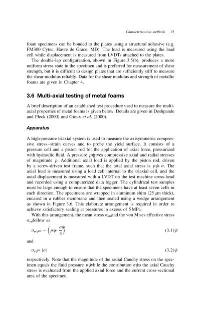
Characterization methods 31<br />
foam specimens can be bonded to the plates using a structural adhesive (e.g.<br />
FM300 Cytec, Havre de Grace, MD). The load is measured using the load<br />
cell while displacement is measured from LVDTs attached to the plates.<br />
The double-lap configureation, shown in Figure 3.5(b), produces a more<br />
uniform stress state in the specimen and is preferred for measurement of shear<br />
strength, but it is difficult to design plates that are sufficiently stiff to measure<br />
the shear modulus reliably. Data for the shear modulus and strength of metallic<br />
foams are given in Chapter 4.<br />
3.6 Multi-axial testing of metal foams<br />
A brief description of an established test procedure used to measure the multiaxial<br />
properties of metal foams is given below. Details are given in Deshpande<br />
and Fleck (2000) and Gioux et al. (2000).<br />
Apparatus<br />
A high-pressure triaxial system is used to measure the axisymmetric compressive<br />
stress–strain curves and to probe the yield surface. It consists of a<br />
pressure cell and a piston rod for the application of axial force, pressurized<br />
with hydraulic fluid. A pressure p gives compressive axial and radial stresses<br />
of magnitude p. Additional axial load is applied by the piston rod, driven<br />
by a screw-driven test frame, such that the total axial stress is p C .The<br />
axial load is measured using a load cell internal to the triaxial cell, and the<br />
axial displacement is measured with a LVDT on the test machine cross-head<br />
and recorded using a computerized data logger. The cylindrical test samples<br />
must be large enough to ensure that the specimens have at least seven cells in<br />
each direction. The specimens are wrapped in aluminum shim (25 µm thick),<br />
encased in a rubber membrane and then sealed using a wedge arrangement<br />
as shown in Figure 3.6. This elaborate arrangement is required in order to<br />
achieve satisfactory sealing at pressures in excess of 5 MPa.<br />
With this arrangement, the mean stress m and the von Mises effective stress<br />
e follow as<br />
and<br />
m D<br />
� �<br />
p C<br />
3<br />
⊲3.1⊳<br />
e D j j ⊲3.2⊳<br />
respectively. Note that the magnitude of the radial Cauchy stress on the specimen<br />
equals the fluid pressure p while the contribution to the axial Cauchy<br />
stress is evaluated from the applied axial force and the current cross-sectional<br />
area of the specimen.