Metal Foams: A Design Guide
Metal Foams: A Design Guide
Metal Foams: A Design Guide
- TAGS
- upload.vnuki.org

Create successful ePaper yourself
Turn your PDF publications into a flip-book with our unique Google optimized e-Paper software.
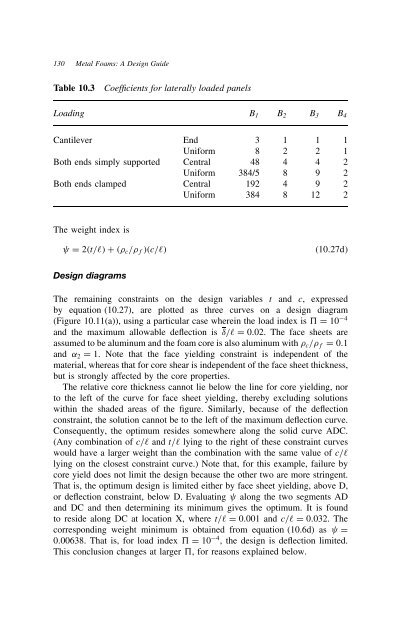
130 <strong>Metal</strong> <strong>Foams</strong>: A <strong>Design</strong> <strong>Guide</strong><br />
Table 10.3 Coefficients for laterally loaded panels<br />
Loading B1 B2 B3 B4<br />
Cantilever End 3 1 1 1<br />
Uniform 8 2 2 1<br />
Both ends simply supported Central 48 4 4 2<br />
Uniform 384/5 8 9 2<br />
Both ends clamped Central 192 4 9 2<br />
Uniform 384 8 12 2<br />
The weight index is<br />
D 2⊲t/ℓ⊳ C ⊲ c/ f⊳⊲c/ℓ⊳ ⊲10.27d⊳<br />
<strong>Design</strong> diagrams<br />
The remaining constraints on the design variables t and c, expressed<br />
by equation (10.27), are plotted as three curves on a design diagram<br />
(Figure 10.11(a)), using a particular case wherein the load index is 5 D 10 4<br />
and the maximum allowable deflection is υ/ℓ D 0.02. The face sheets are<br />
assumed to be aluminum and the foam core is also aluminum with c/ f D 0.1<br />
and ˛2 D 1. Note that the face yielding constraint is independent of the<br />
material, whereas that for core shear is independent of the face sheet thickness,<br />
but is strongly affected by the core properties.<br />
The relative core thickness cannot lie below the line for core yielding, nor<br />
to the left of the curve for face sheet yielding, thereby excluding solutions<br />
within the shaded areas of the figure. Similarly, because of the deflection<br />
constraint, the solution cannot be to the left of the maximum deflection curve.<br />
Consequently, the optimum resides somewhere along the solid curve ADC.<br />
(Any combination of c/ℓ and t/ℓ lying to the right of these constraint curves<br />
would have a larger weight than the combination with the same value of c/ℓ<br />
lying on the closest constraint curve.) Note that, for this example, failure by<br />
core yield does not limit the design because the other two are more stringent.<br />
That is, the optimum design is limited either by face sheet yielding, above D,<br />
or deflection constraint, below D. Evaluating along the two segments AD<br />
and DC and then determining its minimum gives the optimum. It is found<br />
to reside along DC at location X, where t/ℓ D 0.001 and c/ℓ D 0.032. The<br />
corresponding weight minimum is obtained from equation (10.6d) as D<br />
0.00638. That is, for load index 5 D 10 4 , the design is deflection limited.<br />
This conclusion changes at larger 5, for reasons explained below.