Metal Foams: A Design Guide
Metal Foams: A Design Guide
Metal Foams: A Design Guide
- TAGS
- upload.vnuki.org
You also want an ePaper? Increase the reach of your titles
YUMPU automatically turns print PDFs into web optimized ePapers that Google loves.
132 <strong>Metal</strong> <strong>Foams</strong>: A <strong>Design</strong> <strong>Guide</strong><br />
1. Form a rectangular grid of points (t/ℓ, c/ℓ) covering the potential design<br />
space, such as that in Figure 10.11(a).<br />
2. Determine whether each point (t/ℓ, c/ℓ) satisfies all the constraints (10.27):<br />
if it does not, reject it; if it does, evaluate .<br />
3. The point which produces the minimum will be close to the optimum<br />
design. The grid of points can be further refined if necessary.<br />
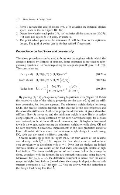
Dependence on load index and core density<br />
The above procedures can be used to bring out the regimes within which the<br />
design is limited by stiffness or strength. Some assistance is provided by reorganizing<br />
equation (10.27) and replotting the design diagram (Figure 10.11(b)).<br />
The constraints are:<br />
⊲face yield⊳ ⊲1/5⊳⊲c/ℓ⊳ � ⊲1/8⊳⊲t/ℓ⊳ 1<br />
⊲core shear⊳<br />
�<br />
fy<br />
⊲1/5⊳⊲c/ℓ⊳ � ⊲1/2⊳ / c �<br />
y<br />
⊲deflection⊳<br />
�<br />
f f<br />
2 y /Ef y<br />
υ/ℓ � 5<br />
C 2<br />
B1⊲t/ℓ⊳⊲c/ℓ⊳ /Gf<br />
�<br />
B2⊲c/ℓ⊳<br />
⊲10.28a⊳<br />
⊲10.28b⊳<br />
⊲10.28c⊳<br />
By plotting ⊲1/5⊳⊲c/ℓ⊳ against t/ℓ using logarithmic axes (Figure 10.11(b))<br />
the respective roles of the relative properties for the core, f y / c y and the stiffness<br />
constraint, υ/ℓ, become apparent. The minimum weight design lies along<br />
DCE. The precise location depends on the specifics of the core properties and<br />
the allowable stiffnesses. As the core properties deteriorate, at given allowable<br />
stiffness, line (3) moves up and the minimum weight is now likely to reside<br />
along segment CE, being controled by the core. Correspondingly, for a given<br />
core material, as the stiffness allowable increases, line (1) displaces downward<br />
towards the origin, again causing the minimum weight to reside along CE and<br />
be core-controled. Conversely, improvements in the core properties and/or a<br />
lower allowable stiffness cause the minimum weight design to reside along<br />
DC, such that the panel is stiffness-controled.<br />
Specific results are plotted in Figure 10.12 for four values of the relative<br />
core density, with υ/ℓ D 0.01. Again, the face sheet material and cellular<br />
core are taken to be aluminum with ˛2 D 1. Note that the designs are indeed<br />
stiffness-limited at low values of the load index and strength-limited at high<br />
load indices. The lower (solid) portion of each curve, below the change in<br />
slope, coincides with the former; the two strength constraints being inactive.<br />
Moreover, for c/ s D 0.3, the deflection constraint is active over the entire<br />
range. At higher load indices (dotted above the change in slope), either or both<br />
strength constraints (10.27(a)) and (10.27(b)) are active, with the deflection at<br />
the design load being less than υ.


