Metal Foams: A Design Guide
Metal Foams: A Design Guide
Metal Foams: A Design Guide
- TAGS
- upload.vnuki.org

You also want an ePaper? Increase the reach of your titles
YUMPU automatically turns print PDFs into web optimized ePapers that Google loves.
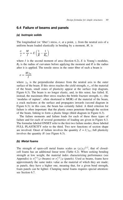
6.4 Failure of beams and panels<br />
(a) Isotropic solids<br />
<strong>Design</strong> formulae for simple structures 69<br />
The longitudinal (or ‘fiber’) stress, , at a point, y, from the neutral axis of a<br />
uniform beam loaded elastically in bending by a moment, M, is<br />
�<br />
M 1<br />
D D E<br />
y I R<br />
�<br />
1<br />
R0<br />
where I is the second moment of area (Section 6.2), E is Young’s modulus,<br />
R0 is the radius of curvature before applying the moment and R is the radius<br />
after it is applied. The tensile stress in the outer fiber of such a beam is<br />
D Mym<br />
I<br />
where ym is the perpendicular distance from the neutral axis to the outer<br />
surface of the beam. If this stress reaches the yield strength, y, ofthematerial<br />
of the beam, small zones of plasticity appear at the surface (top diagram,<br />
Figure 6.3). The beam is no longer elastic, and, in this sense, has failed. If,<br />
instead, the maximum fiber stress reaches the brittle fracture strength, f (the<br />
‘modulus of rupture’, often shortened to MOR) of the material of the beam,<br />
a crack nucleates at the surface and propagates inwards (second diagram in<br />
Figure 6.3); in this case, the beam has certainly failed. A third criterion for<br />
failure is often important: that the plastic zones penetrate through the section<br />
of the beam, linking to form a plastic hinge (third diagram in Figure 6.3).<br />
The failure moments and failure loads for each of these three types of<br />
failure and for each of several geometries of loading are given in Figure 6.3.<br />
The formulae labeled ONSET refer to the first two failure modes; those labeled<br />
FULL PLASTICITY refer to the third. Two new functions of section shape<br />
are involved. Onset of failure involves the quantity Z D I/ym; full plasticity<br />
involves the quantity H (see Figure 6.3).<br />
(b) <strong>Metal</strong> foams<br />
The strength of open-cell metal foams scales as ⊲ / s⊳3/2 , that of closedcell<br />
foams has an additional linear term (Table 4.2). When seeking bending<br />
strength at low weight, the material index characterizing performance (see<br />
Appendix) is 3/2<br />
y / (beams) or 1/2<br />
y<br />
/ (panels). Used as beams, foams have<br />
approximately the same index value as the material of which they are made;<br />
as panels, they have a higher one, meaning that, for a given bend strength,<br />
foam panels can be lighter. Clamping metal foams requires special attention:<br />
see Section 6.7.