Metal Foams: A Design Guide
Metal Foams: A Design Guide
Metal Foams: A Design Guide
- TAGS
- upload.vnuki.org

Create successful ePaper yourself
Turn your PDF publications into a flip-book with our unique Google optimized e-Paper software.
72 <strong>Metal</strong> <strong>Foams</strong>: A <strong>Design</strong> <strong>Guide</strong><br />
A thin-walled elastic tube will buckle inwards under an external pressure<br />
p 0 , given in the last box. Here I refers to the second moment of area of a<br />
section of the tube wall cut parallel to the tube axis.<br />
(b) <strong>Metal</strong> foams<br />
The moduli of open-cell metal foams scale as ⊲ / s⊳ 2 , that of closed-cell<br />
foams has an additional linear term (Table 4.2). When seeking elastic-buckling<br />
resistance at low weight, the material index characterizing performance (see<br />
Appendix) is E 1/2 / (beams) or E 1/3 / (panels). As beam-columns, foams<br />
have the same index value as the material of which they are made; as<br />
panels, they have a higher one, meaning that the foam panel is potentially<br />
lighter for the same buckling resistance. Sandwich structures with foam cores<br />
(Chapter 10) are better still. Clamping metal foams requires special attention:<br />
see Section 6.7.<br />
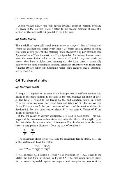
6.6 Torsion of shafts<br />
(a) Isotropic solids<br />
A torque, T, applied to the ends of an isotropic bar of uniform section, and<br />
acting in the plane normal to the axis of the bar, produces an angle of twist<br />
. The twist is related to the torque by the first equation below, in which<br />
G is the shear modulus. For round bars and tubes of circular section, the<br />
factor K is equal to J, the polar moment of inertia of the section, defined in<br />
Section 6.2. For any other section shape K is less than J. ValuesofK are<br />
given in Section 6.2.<br />
If the bar ceases to deform elastically, it is said to have failed. This will<br />
happen if the maximum surface stress exceeds either the yield strength, y, of<br />
the material or the stress at which it fractures. For circular sections, the shear<br />
stress at any point a distance r from the axis of rotation is<br />
D Tr<br />
K D G r<br />
ℓ<br />
The maximum shear stress, max, and the maximum tensile stress, max, are<br />
at the surface and have the values<br />
max D max D Td0<br />
2K<br />
D G d0<br />
2ℓ<br />
If max exceeds y/2 (using a Tresca yield criterion), or if max exceeds the<br />
MOR, the bar fails, as shown in Figure 6.5. The maximum surface stress<br />
for the solid ellipsoidal, square, rectangular and triangular sections is at the