Metal Foams: A Design Guide
Metal Foams: A Design Guide
Metal Foams: A Design Guide
- TAGS
- upload.vnuki.org
Create successful ePaper yourself
Turn your PDF publications into a flip-book with our unique Google optimized e-Paper software.
166 <strong>Metal</strong> <strong>Foams</strong>: A <strong>Design</strong> <strong>Guide</strong><br />
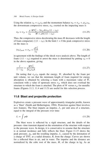
Using the relation vD D cplεD and the momentum balance D D pl C cplvD,<br />
the downstream compressive stress, D, exerted on the impacting mass is<br />
D D<br />
MV<br />
pl C<br />
εD<br />
2 0 2 plAℓεD/⊲1 εD⊳<br />
M C Aℓ/⊲1 εD⊳<br />
⊲11.25⊳<br />
Thus, the compressive stress decelerating the mass M decreases with the length<br />
of foam compacted, ℓ/⊲1<br />
on the mass is<br />
εD⊳. In the limit ℓ D 0 the peak compressive stress<br />
⊲ D⊳peak D pl C V2 0<br />
εD<br />
⊲11.26⊳<br />
in agreement with the findings of the shock wave analysis above. The length of<br />
foam ℓ/⊲1 εD⊳ required to arrest the mass is determined by putting vD D 0<br />
in the above equation, giving<br />
1<br />
ℓ<br />
εD<br />
D MV20 2 plεDA<br />
⊲11.27⊳<br />
On noting that plεD equals the energy, W, absorbed by the foam per<br />
unit volume, we see that the minimum length of foam required for energy<br />
absorption is obtained by selecting a foam with a maximum value of W,<br />
consistent with a value of upstream stress pl which does not overload the<br />
structure to which the foam is attached. The plots of W versus pl for metallic<br />
foams (Figures 11.3, 11.4 and 11.5) are useful for this selection process.<br />
11.6 Blast and projectile protection<br />
Explosives create a pressure wave of approximately triangular profile, known<br />
as a ‘blast’ (Smith and Hetherington, 1994). Protection against blast involves<br />
new features. The blast imparts an impulse, Ji, per unit area of a structure,<br />
equal to the integral of the pressure over time:<br />
�<br />
Ji D pdt ⊲11.28⊳<br />
The blast wave is reflected by a rigid structure, and the details of the<br />
pressure–time transient depend on the orientation of the structure with respect<br />
to the pressure wave. In design, it is conservative to assume that the structure<br />
is at normal incidence and fully reflects the blast. Figure 11.15 shows the<br />
peak pressure, p0, and the resulting impulse, Ji, caused by the detonation of<br />
a charge of TNT, at a radial distance, R, from the charge. Curves are shown<br />
for a reflected blast in air, and in water. The impulse and the distance are<br />
normalized by the cube root of the mass, M, of the charge in kg. As an


