III WVC 2007 - Iris.sel.eesc.sc.usp.br - USP
III WVC 2007 - Iris.sel.eesc.sc.usp.br - USP
III WVC 2007 - Iris.sel.eesc.sc.usp.br - USP

Create successful ePaper yourself
Turn your PDF publications into a flip-book with our unique Google optimized e-Paper software.
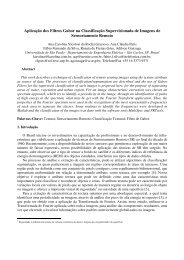
<strong>WVC</strong>'<strong>2007</strong> - <strong>III</strong> Workshop de Visão Computacional, 22 a 24 de Outu<strong>br</strong>o de <strong>2007</strong>, São José do Rio Preto, SP.a localized region in the tissue by a focused ultrasoundpulsed beam. The force causes a displacement which ismeasured by ultrasound pulse-echo techniques. Acousticradiation force produced by a modulated ultrasound beamhas been used to generate shear elastic waves in tissue asan imaging method [18]. In this method, the resulting shearwaves due to the radiation force are generated in the tissue atthe modulation frequency and they are detected by an imagingtransducer.Walker et al. [21] used pulsating acoustic radiation forceto produce images of vi<strong>sc</strong>oelastic parameters in a mimickinggel phantom. Nightingale et al. [14] established theacoustic radiation force impulsive imaging (ARFI) in whicha single transducer is used to generate the localized radiationforce and measure the resulting displacement by meansof ultrasound correlation-based methods. Fatemi et al. [5]proposed vi<strong>br</strong>o-acoustography (VA) as an imaging methodwhich is based on localized dynamic ultrasound radiationforce exerted in tissue by an ultrasound modulated beam.VA is an elastography method in which an o<strong>sc</strong>illatory radiationforce is used to vi<strong>br</strong>ate a small portion of an object(or tissue) in the vicinity of the focal region of the system.The produced acoustic emission from the object vi<strong>br</strong>ationis detected by a hydrophone and it is used to form an imageof the object [6]. Figure 1 shows a diagram of the VAimaging system. The acoustic field emitted carries informa-Figure 1. Ultrasound-stimulated vi<strong>br</strong>oacoustographytion about the local mechanical properties of the object andalso about the contour conditions of the object.In the system de<strong>sc</strong>ribed on Figure 1, the image plane isdefined as the focal plane of the transducer. The transducermechanically <strong>sc</strong>ans an object in raster mode producing animage of the object. The system spatial resolution or powerof resolution, which shows the capacity to distinguish smallclose objects, depends on the distribution of the dynamic radiationforce on the focal region of the transducer.The VA image is formed by pixels whose <strong>br</strong>ightness isdetermined by the acoustic emission of each point in thetissue. The acoustic emission carries information about thetissue region in low and ultrasound frequencies (densityvariation and compressibility), differently from the conventionalultrasound that does not provide this kind of information.This paper presents results of the application of restorationalgorithms in VA images using a digital phantom tosimulate a <strong>br</strong>east with lesion-like inclusions for the experimentaltests. To the best of our knowledge, there are notworks in the literature addressing this problem.2. Vi<strong>br</strong>o-acoustography Image FormationThe general blurring model used in restoration is expressedin space domain byg(x, y, z) =f(x, y, z) ∗ h(x, y, z), (1)where f(x, y, z) is the original image, h(x, y, z) is a blurringfunction, and g(x, y, z) is the blurred image. Moreover,if Gaussian noise is added to the blurring model:g(x, y, z) =f(x, y, z) ∗ h(x, y, z)+n(x, y, z), (2)where n(x, y, z) is the noise and the symbol ∗ denotes thespatial convolution. Independent identically distributed randomvariables are considered in this work.The following equation represents the blurring model inthe frequency domainG(u, v, w) =F (u, v, w)H(u, v, w)+N(u, v, w), (3)where F (u, v, w), G(u, v, w), H(u, v, w) and N(u, v, w)are the Fourier Transforms of f(x, y, z), g(x, y, z), h(x,y, z) and n(x, y, z) respectively.In Ref. [19] the VA image formation is studied takinginto account depth-of-field effects. According to that paper,VA imaging systems might be assumed linear and space invariantin an area nearby the focal region of the system.Thus, the VA image of an object can be obtained convolvingthe function that represents the object with the systemPSF:î(r; ω 0 , ∆ω) =ô(r; ω 0 , ∆ω) ∗ ĥ(r), (4)where r is the position vector of the object, ω 0 is the centerfrequency, ∆ω is the frequency of the dynamic radiationforce produced by the ultrasound beams, and ĥ(r) isthe system PSF. The normalized PSF of the system is givenby:ĥ(r) =A ˆφ 1 (r) ˆφ ∗ 2 (r), (5)where A =[ˆφ 1 (r 0 ) ˆφ ∗ 2 (r 0)] −1 is the normalization constantand the functions ˆφ 1 and ˆφ 2 are the complex amplitudesof the velocity potentials of the ultrasound beams. Figure 2shows a typical VA PSF [19].One can notice the association between the equations (1)and (4), where the functions g, f and h in the first equationare represented by î (VA image), ô (the region or object36