VGB POWERTECH 10 (2019)
VGB PowerTech - International Journal for Generation and Storage of Electricity and Heat. Issue 10 (2019). Technical Journal of the VGB PowerTech Association. Energy is us! Cyber security. Power generation. Environment. Flexibility.
VGB PowerTech - International Journal for Generation and Storage of Electricity and Heat. Issue 10 (2019).
Technical Journal of the VGB PowerTech Association. Energy is us!
Cyber security. Power generation. Environment. Flexibility.
Sie wollen auch ein ePaper? Erhöhen Sie die Reichweite Ihrer Titel.
YUMPU macht aus Druck-PDFs automatisch weboptimierte ePaper, die Google liebt.
<strong>VGB</strong> PowerTech <strong>10</strong> l <strong>2019</strong><br />
Analysis of a grid integrated wind energy conversion system<br />
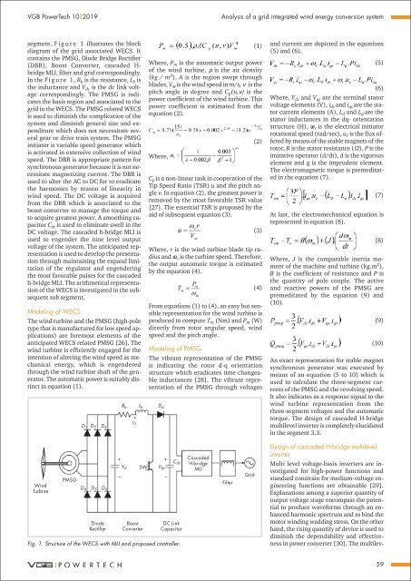
segment. F i g u r e 1 illustrates the block<br />
diagram of the grid associated WECS. It<br />
contains the PMSG, Diode Bridge Rectifier<br />
(DBR), Boost Converter, cascaded H-<br />
bridge MLI, filter and grid correspondingly.<br />
In the F i g u r e 1 , R b is the resistance, L b is<br />
the inductance and V dc is the dc link voltage<br />
correspondingly. The PMSG is indicates<br />
the basis region and associated to the<br />
grid in the WECS. The PMSG related WECS<br />
is used to diminish the complication of the<br />
system and diminish general size and expenditure<br />
which does not necessitate several<br />
gear or drive train system. The PMSG<br />
initiator is variable speed generator which<br />
is activated in extensive collection of wind<br />
speed. The DBR is appropriate pattern for<br />
synchronous generator because it is not necessitate<br />
magnetizing current. The DBR is<br />
used to alter the AC to DC for to eradicate<br />
the harmonics by reason of linearity in<br />
wind speed. The DC voltage is acquired<br />
from the DBR which is associated to the<br />
boost converter to manage the torque and<br />
to acquire greatest power. A smoothing capacitor<br />
C dc is used to eliminate swell in the<br />
DC voltage. The cascaded h-bridge MLI is<br />
used to engender the nine level output<br />
voltage of the system. The anticipated representation<br />
is used to develop the presentation<br />
through maintaining the expand limitation<br />
of the regulator and engendering<br />
the most favorable pulses for the cascaded<br />
h-bridge MLI. The arithmetical representation<br />
of the WECS is investigated in the subsequent<br />
sub segment.<br />
Modeling of WECS<br />
The wind turbine and the PMSG (high-pole<br />
type that is manufactured for low speed applications)<br />
are foremost elements of the<br />
anticipated WECS related PMSG [26]. The<br />
wind turbine is efficiently engaged for the<br />
intention of altering the wind speed as mechanical<br />
energy, which is engendered<br />
through the wind turbine shaft of the generator.<br />
The automatic power is suitably distinct<br />
in equation (1).<br />
<br />
(1)<br />
Where, P m is the automatic output power<br />
of the wind turbine, is the air density<br />
(kg / m 3 ), A is the region swept through<br />
blades, V is the wind speed in m/s, is the<br />
pitch angle in degree and C p (u,) is the<br />
power coefficient of the wind turbine. This<br />
power coefficient is estimated from the<br />
equation (2).<br />
(2)<br />
Where,<br />
R b L b D d<br />
i b<br />
C p is a non-linear task in cooperation of the<br />
Tip Speed Ratio (TSR) u and the pitch angle<br />
. In equation (2), the greatest power is<br />
removed by the most favorable TSR value<br />
[27]. The essential TSR is proposed by the<br />
aid of subsequent equation (3).<br />
<br />
(3)<br />
Where, r is the wind turbine blade tip radius<br />
and r is the turbine speed. Therefore,<br />
the output automatic torque is estimated<br />
by the equation (4).<br />
(4)<br />
From equations (1) to (4), an easy but sensible<br />
representation for the wind turbine is<br />
produced to compute T m (Nm) and P m (W)<br />
directly from rotor angular speed, wind<br />
speed and the pitch angle.<br />
Modeling of PMSG<br />
The vibrant representation of the PMSG<br />
is indicating the rotor d-q orientation<br />
structure which eradicates time changeable<br />
inductances [28]. The vibrant representation<br />
of the PMSG through voltages<br />
and current are depicted in the equations<br />
(5) and (6).<br />
<br />
(5)<br />
(6)<br />
Where, V ds and V qs are the terminal stator<br />
voltage elements (V), i ds and i qs are the stator<br />
current elements (A), L d and L q are the<br />
stator inductances in the dq- orientation<br />
structure (H), r is the electrical initiator<br />
rotational speed (rad/sec), u r is the flux offered<br />
by means of the stable magnets of the<br />
rotor, R is the stator resistance (), P is the<br />
imitative operator (d/dt), d is the vigorous<br />
element and q is the imprudent element.<br />
The electromagnetic torque is premeditated<br />
in the equation (7).<br />
(7)<br />
At last, the electromechanical equation is<br />
represented in equation (8).<br />
(8)<br />
Where, J is the comparable inertia moment<br />
of the machine and turbine (kg.m 2 ),<br />
B is the coefficient of resistance and P is<br />
the quantity of pole couple. The active<br />
and reactive powers of the PMSG are<br />
premeditated by the equation (9) and<br />
(<strong>10</strong>).<br />
(9)<br />
<br />
(<strong>10</strong>)<br />
An exact representation for stable magnet<br />
synchronous generator was executed by<br />
means of an equation (5 to <strong>10</strong>) which is<br />
used to calculate the three-segment currents<br />
of the PMSG and the revolving speed.<br />
It also indicates as a response signal to the<br />
wind turbine representation from the<br />
three-segment voltages and the automatic<br />
torque. The design of cascaded H-bridge<br />
multilevel inverter is completely elucidated<br />
in the segment 3.3.<br />
Wind<br />
Turbine<br />
PMSG<br />
D 1 D 2 D 3<br />
+<br />
D 4 D 5 D 6<br />
Diode<br />
Rectifier<br />
–<br />
V d<br />
SW<br />
Boost<br />
Converter<br />
DC Link<br />
Capacitor<br />
Fig. 1. Structure of the WECS with MLI and proposed controller.<br />
V dc<br />
+<br />
–<br />
C dc<br />
Cascaded<br />
H-bridge<br />
MLI<br />
Filter<br />
Grid<br />
Design of cascaded H-bridge multilevel<br />
inverter<br />
Multi level voltage-basis inverters are investigated<br />
for high-power functions and<br />
standard constrain for medium-voltage engineering<br />
functions are obtainable [29].<br />
Explanations among a superior quantity of<br />
output voltage stage encompass the potential<br />
to produce waveforms through an enhanced<br />
harmonic spectrum and to bind the<br />
motor winding wadding stress. On the other<br />
hand, the rising quantity of device is used to<br />
diminish the dependability and effectiveness<br />
in power converter [30]. The multilev-<br />
59


