

VGB POWERTECH 10 (2019)
VGB PowerTech - International Journal for Generation and Storage of Electricity and Heat. Issue 10 (2019). Technical Journal of the VGB PowerTech Association. Energy is us! Cyber security. Power generation. Environment. Flexibility.
VGB PowerTech - International Journal for Generation and Storage of Electricity and Heat. Issue 10 (2019).
Technical Journal of the VGB PowerTech Association. Energy is us!
Cyber security. Power generation. Environment. Flexibility.

Sie wollen auch ein ePaper? Erhöhen Sie die Reichweite Ihrer Titel.
YUMPU macht aus Druck-PDFs automatisch weboptimierte ePaper, die Google liebt.
Analysis of a grid integrated wind energy conversion system <strong>VGB</strong> PowerTech <strong>10</strong> l <strong>2019</strong><br />
Tab. 2. Implementation parameters of the<br />
proposed method.<br />
Fig. 7. Matlab/Simulink model of the proposed method with cascaded H-bridge multilevel<br />
inverter.<br />
anticipated process is depicted in the subsequent<br />
segment.<br />
Case 1: Analysis of normal wind speed<br />
Case 2: Analysis of varied wind speed<br />
Analysis of Case 1<br />
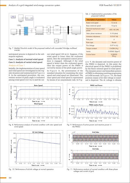
Initially, the implementation of rotor speed<br />
and wind speed are investigated in the regular<br />
situation and summarized in F i g u r e s<br />
8 . In the anticipated procedure, the convenient<br />
section of pitch angle is evaluated<br />
among wind speed (12.5 m/s) and the cutout<br />
wind speed (24 m/s). Suppose, if the<br />
wind speed is lesser than the evaluated<br />
speed, then the anticipated control procedure<br />
is engaged. Although if the wind<br />
speed is better than the evaluated speed,<br />
then the output power of the PMSG is<br />
curved by means of the pitch angle power.<br />
In F i g u r e 8 , the presentation of the<br />
standard situation for examining the rotor<br />
speed and wind speed are illustrated. The<br />
rotor speed and wind speed is represented<br />
by means of an unsystematic task. In F i g -<br />
Description of parameters<br />
Rated wind speed<br />
Base rotational speed<br />
Nominal mechanical output<br />
power<br />
Stator phase resistance<br />
Armature inductance<br />
Values<br />
12 (m/s)<br />
12 (p/u)<br />
605.142 (W)<br />
0.18 (obm)<br />
0.0167 (H)<br />
Pole pairs 4<br />
Rotor type<br />
Round<br />
Flux linkage 0.0714 (V s )<br />
Torque constant 0.4286 (N m )<br />
Inertia 0.00062 J(kgm -2 )<br />
Friction factor 0.00030<br />
F(N ms )<br />
u r e 9 , the dynamic and reactive power of<br />
the PMSG is depicted. At this point the<br />
electrical speed of the PMSG is prohibited<br />
by the finest rational speed in wind speed.<br />
The dynamic power and immediate powers<br />
of PMSG is obtaining resolving progression<br />
at 0.458 seconds. In F i g u r e <strong>10</strong> , the fixed<br />
position output of dc-link voltage at standard<br />
is depicted. The dc voltage is obtains<br />
1,500<br />
Rotor Speed<br />
80<br />
PMSG real Power<br />
Speed in m/s<br />
1,000<br />
500<br />
0<br />
0 0.05 0.1 0.15 0.2 0.25 0.3 0.35 0.4 0.45 0.5<br />
Time in sec<br />
Wind Speed<br />
15<br />
P<br />
60<br />
40<br />
20<br />
0<br />
0 0.05 0.1 0.15 0.2 0.25 0.3 0.35 0.4 0.45 0.5<br />
Time in sec<br />
PMSG reative Power<br />
0.04<br />
Speed in rpm/s<br />
<strong>10</strong><br />
5<br />
0<br />
0 0.05 0.1 0.15 0.2 0.25 0.3 0.35 0.4 0.45 0.5<br />
Time in sec<br />
Q<br />
0.03<br />
0.02<br />
0.01<br />
0<br />
0 0.05 0.1 0.15 0.2 0.25 0.3 0.35 0.4 0.45 0.5<br />
Time in sec<br />
Fig. 8. Performance analysis of normal condition with rotor speed and<br />
wind speed.<br />
Fig. 9. Performance of active power and reactive power in<br />
the PMSG.<br />
300<br />
DC Link Voltage<br />
x<strong>10</strong> 4<br />
2<br />
Grid Vabc<br />
250<br />
0<br />
Voltage in V<br />
><br />
200<br />
150<br />
<strong>10</strong>0<br />
-2<br />
0 0.05 0.1 0.15 0.2 0.25 0.3 0.35 0.4 0.45 0.5<br />
Time in sec<br />
Grid Iabc<br />
20<br />
<strong>10</strong><br />
50<br />
0<br />
0 0.05 0.1 0.15 0.2 0.25 0.3 0.35 0.4 0.45 0.5<br />
Time in sec<br />
A<br />
0<br />
-<strong>10</strong><br />
-20<br />
0 0.05 0.1 0.15 0.2 0.25 0.3 0.35 0.4 0.45 0.5<br />
Time in sec<br />
Fig. <strong>10</strong>. Performance of dc-link voltage at normal operation<br />
Fig. 11. Performance analysis of normal condition with three phase<br />
voltage and current of grid.<br />
64


