

VGB POWERTECH 10 (2019)
VGB PowerTech - International Journal for Generation and Storage of Electricity and Heat. Issue 10 (2019). Technical Journal of the VGB PowerTech Association. Energy is us! Cyber security. Power generation. Environment. Flexibility.
VGB PowerTech - International Journal for Generation and Storage of Electricity and Heat. Issue 10 (2019).
Technical Journal of the VGB PowerTech Association. Energy is us!
Cyber security. Power generation. Environment. Flexibility.

Sie wollen auch ein ePaper? Erhöhen Sie die Reichweite Ihrer Titel.
YUMPU macht aus Druck-PDFs automatisch weboptimierte ePaper, die Google liebt.
Analysis of a grid integrated wind energy conversion system <strong>VGB</strong> PowerTech <strong>10</strong> l <strong>2019</strong><br />
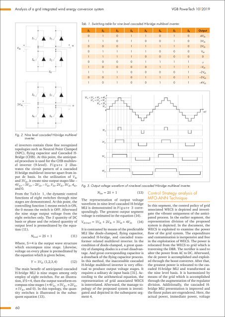
Tab. 1. Switching table for nine level cascaded H-bridge multilevel inverter.<br />
S 1 S 2 S 3 S 4 S 5 S 6 S 7 S 8 Output<br />
V dc<br />
+<br />
-<br />
S 1 S 3<br />
S 4<br />
S 2<br />
S 4<br />
+ a<br />
0 1 0 1 1 0 1 0 4V dc<br />
1 1 0 1 0 0 1 0 3V dc<br />
0 0 0 1 1 1 1 0 2V dc<br />
0 1 1 1 1 0 0 0 V dc<br />
1 1 1 1 0 0 0 0 0<br />
0 0 0 0 1 1 1 1 0<br />
1 0 0 0 0 1 1 1 –V dc<br />
1 1 1 0 0 0 0 1 –2V dc<br />
0 0 1 0 1 1 0 1 –3V dc<br />
1 0 1 0 0 1 0 1 –4V dc<br />
S 5 S 7<br />
+<br />
3V dc<br />
-<br />
-<br />
o<br />
S 8 S 6<br />
Fig. 2. Nine level cascaded H-bridge multilevel<br />
inverter.<br />
el inverters contain three fine recognized<br />
topologies such as Neutral Point Clamped<br />
(NPC), flying capacitor and Cascaded H-<br />
Bridge (CHB). At this point, the anticipated<br />
procedure is used for the CHB multilevel<br />
inverter (9-level). F i g u r e 2 illustrates<br />
the circuit pattern of a cascaded<br />
H-bridge multilevel inverter apart from input<br />
dc basis. In the utilization of V dc<br />
and 3V dc , it create nine output stages like –<br />
4V dc , – 3V dc , – 2V dc , – V dc , V dc , 2V dc , 3V dc , 4 dc ,<br />
and 0.<br />
From the Ta b l e 1 , the dynamic control<br />
functions of eight switches through nine<br />
stages are demonstrated. At this point, the<br />
controlling function 1 means switch is ON,<br />
the 0 means the switch is OFF. Afterward<br />
the nine stage output voltage from the<br />
eight switches only. The S quantity of DC<br />
basis or phase and the related quantity of<br />
output level is premeditated by the equation<br />
(11).<br />
N level = 2S + 1 (11)<br />
Where, S=4 is the output wave structure<br />
which encompass nine stage. Likewise,<br />
voltage on every phase is premeditated by<br />
the equation which is given below,<br />
Y = 1V dc (1,2,3,4) (12)<br />
The main benefit of anticipated cascaded<br />
H-bridge MLI is nine stages among only<br />
employ of eight switches. For an illustration,<br />
if S=4, then the output waveform encompass<br />
nine stages (±4V dc , ±3V dc , ±2V dc ,<br />
±1V dc , and 0). In this topology, the quantity<br />
switches is illustrated in the subsequent<br />
equation (13).<br />
Fig. 3. Output voltage waveform of nine-level cascaded H-bridge multilevel inverter.<br />
N Sw = 2S + 1 (13)<br />
The representation of output voltage<br />
waveform in nine-level cascaded H-bridge<br />
MLI is demonstrated in F i g u r e 3 correspondingly.<br />
The greatest output segment<br />
voltage is estimated in the equation (14).<br />
V dc(out) = 1V dc + 2V dc + 3V dc + 4V dc (14)<br />
It is contrasted by means of the predictable<br />
MLI like diode-clamped, flying capacitor,<br />
cascaded H-bridge, and cascaded transformer<br />
related multilevel inverter. In the<br />
condition of diode-clamped, a great quantity<br />
of clamping diodes is a cruel disadvantage.<br />
And great corresponding capacitor is<br />
a drawback of the flying capacitor process.<br />
In this method, the inaccessible cascaded<br />
H-bridge multilevel inverter is very effectual<br />
to produce output voltage stages. It<br />
requires a solitary dc input basis [31]. According<br />
to the arithmetical equation, the<br />
representation of grid associated WECS<br />
is interrelated. Afterward, the manage topology<br />
of the proposed system is investigated<br />
and depicted in the subsequent segment<br />
4.<br />
Control Strategy analysis of<br />
MFO-ANN Technique<br />
In this segment, the control policy of grid<br />
associated WECS is depicted and investigate<br />
the vibrant uniqueness of the anticipated<br />
process. In the earlier segment, the<br />
representation division of the proposed<br />
system is depicted. In the document, the<br />
WECS is exploited to examine the power<br />
flow of the grid system. The expenditure<br />
and contamination is inexpensive and free<br />
in the exploitation of WECS. The power is<br />
relocated from the WECS to grid which is<br />
traversing the DBR. The rectifier is used to<br />
alter the power from AC to DC. Afterward,<br />
the dc power is accomplished and exploited<br />
through the boost converter. After that,<br />
the greatest power is relocated to the cascaded<br />
H-bridge MLI and transformed as<br />
the nine level basis. It is harmonized by<br />
means of the grid which is accomplished<br />
through the augmentation of the regulator<br />
division. Additionally, the cascaded H-<br />
bridge MLI presentation is improved and<br />
the finest pulses are engendered. Here, the<br />
actual power, immediate power, voltage<br />
60


