

3. - Fagor Automation
3. - Fagor Automation
3. - Fagor Automation

Create successful ePaper yourself
Turn your PDF publications into a flip-book with our unique Google optimized e-Paper software.
Operating manual<br />
<strong>3.</strong><br />
EXECUTE / SIMULATE<br />
Graphics<br />
CNC 8035<br />
·T· MODEL<br />
(SOFT V16.3X)<br />
·80·<br />
<strong>3.</strong>5.7 Measurement<br />
To use this function, a line graphics (planes XZ, XC or ZC) must be selected and the CNC must not<br />
be executing or simulating the part-program. If this is the case, it must be interrupted.<br />
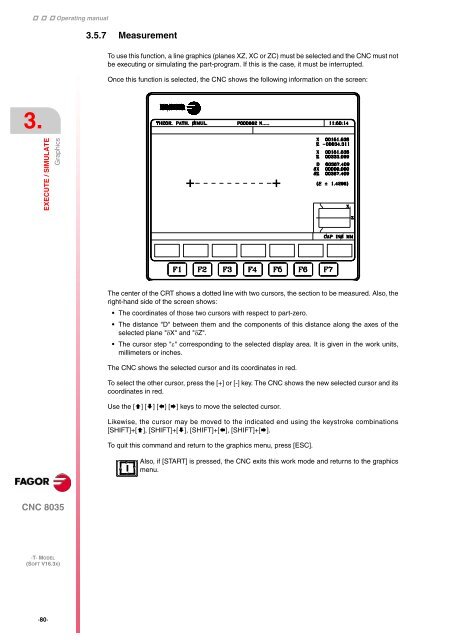
Once this function is selected, the CNC shows the following information on the screen:<br />
The center of the CRT shows a dotted line with two cursors, the section to be measured. Also, the<br />
right-hand side of the screen shows:<br />
The coordinates of those two cursors with respect to part-zero.<br />
The distance "D" between them and the components of this distance along the axes of the<br />
selected plane "X" and "Z".<br />
The cursor step "" corresponding to the selected display area. It is given in the work units,<br />
millimeters or inches.<br />
The CNC shows the selected cursor and its coordinates in red.<br />
To select the other cursor, press the [+] or [-] key. The CNC shows the new selected cursor and its<br />
coordinates in red.<br />
Use the [] [] [] [] keys to move the selected cursor.<br />
Likewise, the cursor may be moved to the indicated end using the keystroke combinations<br />
[SHIFT]+[], [SHIFT]+[], [SHIFT]+[], [SHIFT]+[].<br />
To quit this command and return to the graphics menu, press [ESC].<br />
Also, if [START] is pressed, the CNC exits this work mode and returns to the graphics<br />
menu.


