- Page 1 and 2: CNC 8065 Canned cycles (·M· model
- Page 3 and 4: Canned cycles (·M· model) INDEX A
- Page 5 and 6: Canned cycles (·M· model) ABOUT T
- Page 7: Canned cycles (·M· model) Softwar
- Page 11: Canned cycles (·M· model) VERSION
- Page 14 and 15: CNC 8065 (REF: 1209) ·14· PRECAUT
- Page 17 and 18: Canned cycles (·M· model) WARRANT
- Page 19: Canned cycles (·M· model) MATERIA
- Page 23 and 24: MILLING CANNED CYCLES. 1.1 General
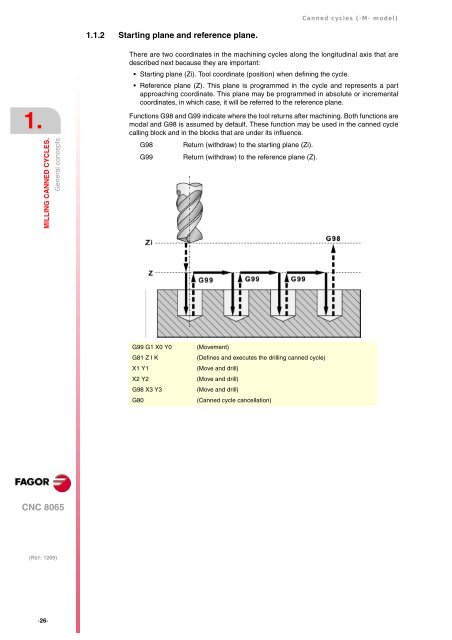
- Page 25: Canned cycles (·M· model) 1.1.1 D
- Page 29 and 30: Canned cycles (·M· model) Example
- Page 31 and 32: Canned cycles (·M· model) T1 M6 G
- Page 33 and 34: Canned cycles (·M· model) 1.2.1 P
- Page 35 and 36: Canned cycles (·M· model) K Dwell
- Page 37 and 38: Canned cycles (·M· model) 1.3.1 P
- Page 39 and 40: Canned cycles (·M· model) 4 Dwell
- Page 41 and 42: Canned cycles (·M· model) 1.5 G84
- Page 43 and 44: Canned cycles (·M· model) 1.5.1 P
- Page 45 and 46: Canned cycles (·M· model) 1.6.1 P
- Page 47 and 48: Canned cycles (·M· model) E Dista
- Page 49 and 50: Canned cycles (·M· model) 1.8 G87
- Page 51 and 52: Canned cycles (·M· model) 3 Rapid
- Page 53 and 54: Canned cycles (·M· model) 1.9 G88
- Page 55 and 56: Canned cycles (·M· model) 4 Penet
- Page 57 and 58: Canned cycles (·M· model) 1.10 G2
- Page 59 and 60: Canned cycles (·M· model) 1.11 G2
- Page 61 and 62: Canned cycles (·M· model) 7 Rapid
- Page 63 and 64: Canned cycles (·M· model) L Finis
- Page 65 and 66: MULTIPLE MACHINING 2 The programmer
- Page 67 and 68: Canned cycles (·M· model) Basic o
- Page 69 and 70: Canned cycles (·M· model) 2.2 G16
- Page 71 and 72: Canned cycles (·M· model) 2.2.1 P
- Page 73 and 74: Canned cycles (·M· model) Y J Y D
- Page 75 and 76: Canned cycles (·M· model) 2.4 G16
- Page 77 and 78:
Canned cycles (·M· model) 2.4.1 P
- Page 79 and 80:
Canned cycles (·M· model) Basic o
- Page 81 and 82:
Canned cycles (·M· model) 2.6 G16
- Page 83 and 84:
CYCLE EDITOR 3 The cycle editor is
- Page 85 and 86:
Canned cycles (·M· model) 3.1 Con
- Page 87 and 88:
Canned cycles (·M· model) 3.3 Sel
- Page 89 and 90:
Canned cycles (·M· model) If the
- Page 91 and 92:
CANNED CYCLES OF THE EDITOR 4.1 Can
- Page 93 and 94:
Canned cycles (·M· model) 4.1.2 W
- Page 95 and 96:
Canned cycles (·M· model) 4.1.3 V
- Page 97 and 98:
Canned cycles (·M· model) 4.2 Cen
- Page 99 and 100:
Canned cycles (·M· model) 4.2.1 B
- Page 101 and 102:
Canned cycles (·M· model) 4.3.1 B
- Page 103 and 104:
Canned cycles (·M· model) 4.4.1 B
- Page 105 and 106:
Canned cycles (·M· model) Spindle
- Page 107 and 108:
Canned cycles (·M· model) 4.6 Tap
- Page 109 and 110:
Canned cycles (·M· model) 4.6.1 B
- Page 111 and 112:
Canned cycles (·M· model) Machini
- Page 113 and 114:
Canned cycles (·M· model) 4.8 Rea
- Page 115 and 116:
Canned cycles (·M· model) 4.9 Bor
- Page 117 and 118:
Canned cycles (·M· model) 4.10 Bo
- Page 119 and 120:
Canned cycles (·M· model) 4.10.1
- Page 121 and 122:
Canned cycles (·M· model) I Penet
- Page 123 and 124:
Canned cycles (·M· model) 4.11.1
- Page 125 and 126:
Canned cycles (·M· model) Type of
- Page 127 and 128:
Canned cycles (·M· model) θ Pene
- Page 129 and 130:
Canned cycles (·M· model) 4.13 Ci
- Page 131 and 132:
Canned cycles (·M· model) The fin
- Page 133 and 134:
Canned cycles (·M· model) 4.13.1
- Page 135 and 136:
Canned cycles (·M· model) F Surfa
- Page 137 and 138:
Canned cycles (·M· model) 4.14.1
- Page 139 and 140:
Canned cycles (·M· model) 4.15 2D
- Page 141 and 142:
Canned cycles (·M· model) T Rough
- Page 143 and 144:
Canned cycles (·M· model) 4.15.1
- Page 145 and 146:
Canned cycles (·M· model) 4.15.3
- Page 147 and 148:
Canned cycles (·M· model) New pro
- Page 149 and 150:
Canned cycles (·M· model) P.XY Na
- Page 151 and 152:
Canned cycles (·M· model) Fz Pene
- Page 153 and 154:
Canned cycles (·M· model) Program
- Page 155 and 156:
Canned cycles (·M· model) 4.16.2
- Page 157 and 158:
Canned cycles (·M· model) Configu
- Page 159 and 160:
Canned cycles (·M· model) 4.17 Re
- Page 161 and 162:
Canned cycles (·M· model) Program
- Page 163 and 164:
Canned cycles (·M· model) 4.17.1
- Page 165 and 166:
Canned cycles (·M· model) I Penet
- Page 167 and 168:
Canned cycles (·M· model) 4.18.1
- Page 169 and 170:
Canned cycles (·M· model) Z Part
- Page 171 and 172:
Canned cycles (·M· model) 4.19.1
- Page 173 and 174:
Canned cycles (·M· model) The rou
- Page 175 and 176:
Canned cycles (·M· model) 4.20.1
- Page 177 and 178:
Canned cycles (·M· model) F Surfa
- Page 179 and 180:
Canned cycles (·M· model) 4.21.1
- Page 181 and 182:
Canned cycles (·M· model) The rou
- Page 183 and 184:
Canned cycles (·M· model) Program
- Page 185 and 186:
Canned cycles (·M· model) 5 Rapid
- Page 187 and 188:
Canned cycles (·M· model) 4.24 Mu
- Page 189 and 190:
Canned cycles (·M· model) 4.25 Mu
- Page 191 and 192:
Canned cycles (·M· model) 4.27 Ra
- Page 193 and 194:
Canned cycles (·M· model) CNC 806