

5800 Refrigerated Sampler Service Guide - Isco
5800 Refrigerated Sampler Service Guide - Isco
5800 Refrigerated Sampler Service Guide - Isco

You also want an ePaper? Increase the reach of your titles
YUMPU automatically turns print PDFs into web optimized ePapers that Google loves.
<strong>5800</strong> <strong>Refrigerated</strong> <strong>Sampler</strong> <strong>Service</strong> <strong>Guide</strong><br />
Section 2 Sample Delivery System<br />
2.2.1 Pump Tubing Removal If the pump tube will be used in the new pump, remove the tube<br />
before removing the pump module.<br />
1. Disconnect power from the sampler to ensure that it will<br />
not attempt to operate the pump.<br />
2. Loosen the Liquid Detector Cover (F) by unscrewing the<br />
large black knob (H).<br />
3. Unlatch the Pump Housing Band (J).<br />
4. Pull the tube (A) away from the bulkhead fitting (B) and<br />
disconnect the tubing coupler and suction line.<br />
5. Pull the tube out through the pump.<br />
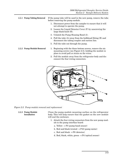
2.2.2 Pump Module Removal 1. Beginning with the three bottom screws, remove the six<br />
mounting screws (see Figure 2-2), holding the module in<br />
place to avoid pull or strain on the wires.<br />
2. Pull the module away from the refrigerator body and disconnect<br />
the four wiring connectors.<br />
Figure 2-2 Pump module removal and replacement<br />
2.2.3 Pump Module<br />
Installation<br />
Clean the pump module mounting surface on the refrigerator<br />
body. This will help ensure that the gasket on the new module<br />
will seal the enclosure.<br />
1. Attach the four wiring connectors from the new pump module<br />
to the pump interface board:<br />
a. Yellow P3 (pump band sensor)<br />
b. Red and black twisted P10 (pump motor)<br />
c. Red and black P8 (detector)<br />
d. Red, black, white, green P4 (optical sensor)<br />
2-3


