

5800 Refrigerated Sampler Service Guide - Isco
5800 Refrigerated Sampler Service Guide - Isco
5800 Refrigerated Sampler Service Guide - Isco

Create successful ePaper yourself
Turn your PDF publications into a flip-book with our unique Google optimized e-Paper software.
<strong>5800</strong> <strong>Refrigerated</strong> <strong>Sampler</strong> <strong>Service</strong> <strong>Guide</strong><br />
Section 2 Sample Delivery System<br />
2.3 Pump Disassembly<br />
and Parts<br />
Replacement<br />
For module removal and replacement steps, see Section 2.2.<br />
This section details the replacement steps for pump components.<br />
2.3.1 Pump Part Numbers Table 2-1 contains a list of the pump’s components with part<br />
numbers.<br />
Part<br />
Table 2-1 Pump Parts List<br />
Number<br />
Thumb screw 60-4704-055<br />
O-ring 202-5000-07<br />
Gasket 60-3113-029<br />
Pump shaft assembly 60-4708-002<br />
Idler gear 60-4708-017<br />
Motor plate 60-4708-018<br />
Motor and gear assembly 60-4704-014<br />
Motor wiring assembly 69-4704-027<br />
Optical disk 60-9003-112<br />
Pump band 60-4704-032<br />
Pump housing cover 60-4704-036<br />
Pump cover bushing 60-3703-278<br />
Optical sensor wiring assembly 69-4704-025<br />
Hold-down kit for detector barrier 68-4700-037<br />
Pump base with detector 60-4704-141<br />
Pump cover installation kit 68-4700-101<br />
Pump heater kit 115 VAC 68-4700-104<br />
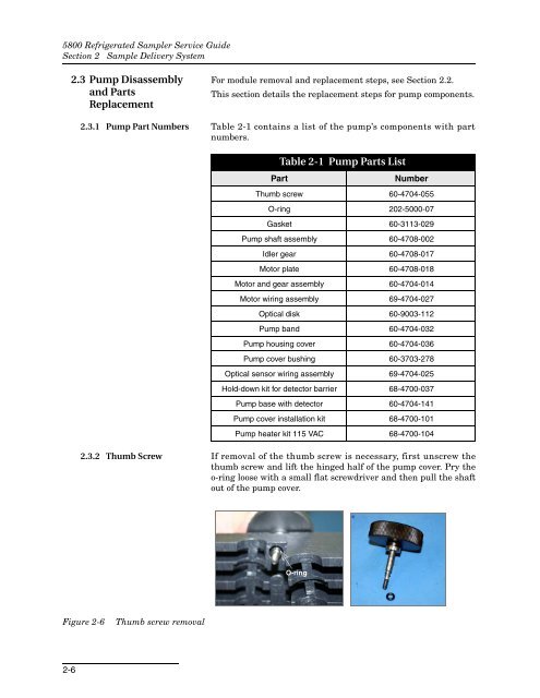
2.3.2 Thumb Screw If removal of the thumb screw is necessary, first unscrew the<br />
thumb screw and lift the hinged half of the pump cover. Pry the<br />
o-ring loose with a small flat screwdriver and then pull the shaft<br />
out of the pump cover.<br />
O-ring<br />
Figure 2-6<br />
Thumb screw removal<br />
2-6


