Superconducting Technology Assessment - nitrd
Superconducting Technology Assessment - nitrd
Superconducting Technology Assessment - nitrd

Create successful ePaper yourself
Turn your PDF publications into a flip-book with our unique Google optimized e-Paper software.
ground plane may be located either below the trilayer or, less<br />
often, on the top. Optical photolithography (either g-line or<br />
i-line) is used to transfer the mask design to the photoresist<br />
in most cases. E-beam lithography is also used to write the<br />
smallest features ( 1 m) in some processes. The features<br />
are then patterned by a variety of methods including etching<br />
by reactive ion etching (RIE) or inductively coupled plasma<br />
(ICP) etching, anodization, and liftoff. The integrated circuit<br />
fabrication processes are discussed in more detail below.<br />
B. Fabrication Challenges<br />
The challenges in the fabrication of superconductor<br />
integrated circuits fall broadly into two categories: improving<br />
parametric performance and minimizing process-induced<br />
defects. Parametric performance involves the targeting<br />
of important device parameters and minimizing device variation,<br />
both on a local and global scale. We discuss this in<br />
more detail in Section V. Process defects include unwanted<br />
contamination, lack of integrity in wiring or dielectrics,<br />
etc., and are typically represented as defect density. Even<br />
for modest feature sizes (i.e., 1 m), defect density is an<br />
important consideration and care must be taken to minimize<br />
contributions from the environment, while working to reduce<br />
contributions from the process itself. These challenges<br />
are similar to those faced by the semiconductor industry,<br />
because many of the tools, methods, and materials are<br />
similar. We have adopted solutions already developed by<br />
the semiconductor industry and adapted them to the specific<br />
needs of superconductor integrated circuit manufacturing.<br />
For example, class 100 to class 10 clean rooms, depending<br />
on the level of integration, and clean room process tools,<br />
such as load-locked vacuum systems and automated wafer<br />
handling, are used to minimize defects.<br />
Much work has been done over the past decade to minimize<br />
process-induced defects. Process improvements to<br />
address dielectric integrity included the use of sputtered<br />
SiO as a replacement for evaporated SiO, which helped<br />
to reduce pinhole density in the interlevel dielectric and<br />
improved step coverage of the overlying metal layer. Implementation<br />
of bias-sputtered SiO was another improvement<br />
that further improved dielectric integrity and improved metal<br />
step coverage [41]. Another approach to improved step coverage<br />
is the use of electron cyclotron resonance (ECR)<br />
plasma-enhanced chemical vapor deposition (PECVD)<br />
SiO , which provides a collateral benefit of improved junction<br />
characteristics [20], [42].<br />
Another challenge in superconductor integrated circuit<br />
fabrication is addressing material properties limitations for<br />
materials such as niobium nitride. Unlike niobium in which<br />
the Nb/Al-AlO /Nb trilayer is relatively straightforward<br />
to produce with good uniformity, the tunnel barrier for<br />
niobium nitride is more challenging. Sputter-deposited<br />
MgO and AlN are the typical material choices for tunnel<br />
barriers [37], [43]. Controlling the thickness (on the order<br />
of 1 nm) and uniformity (to better than 0.01 nm!) of an<br />
ultrathin barrier such as MgO is difficult by conventional<br />
sputter deposition techniques. Accurate targeting of junction<br />
becomes very difficult because is an exponential<br />
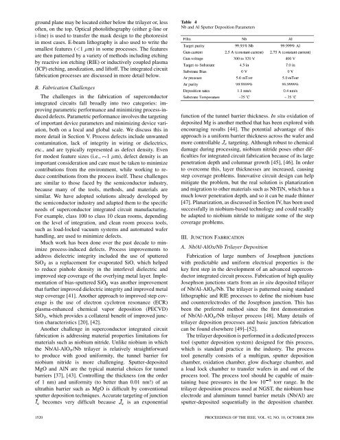
Table 4<br />
Nb and Al Sputter Deposition Parameters<br />
function of the tunnel barrier thickness. In situ oxidation of<br />
deposited Mg is another method that has been explored with<br />
encouraging results [44]. The potential advantage of this<br />
approach is a uniform barrier thickness across the wafer and<br />
more controllable targeting. Although robust to chemical<br />
damage during processing, niobium nitride poses other difficulties<br />
for integrated circuit fabrication because of its large<br />
penetration depth and columnar growth [45], [46]. In order<br />
to overcome this, layer thicknesses are increased, causing<br />
step coverage problems. Innovative circuit design can help<br />
mitigate the problem, but the real solution is planarization<br />
and migration to other materials such as NbTiN, which has a<br />
much lower penetration depth, and so it can be made thinner<br />
[47]. Planarization, as discussed in Section IV, has been used<br />
successfully in niobium-based technology and could readily<br />
be adapted to niobium nitride to mitigate some of the step<br />
coverage problems.<br />
III. JUNCTION FABRICATION<br />
A. Nb/Al-AlOx/Nb Trilayer Deposition<br />
Fabrication of large numbers of Josephson junctions<br />
with predictable and uniform electrical properties is the<br />
key first step in the development of an advanced superconductor<br />
integrated circuit process. Fabrication of high quality<br />
Josephson junctions starts from an in situ deposited trilayer<br />
of Nb/Al-AlO /Nb. The trilayer is patterned using standard<br />
lithographic and RIE processes to define the niobium base<br />
and counterelectrodes of the Josephson junction. This has<br />
been the preferred method since the first demonstration<br />
of Nb/Al-AlO /Nb trilayer process [48]. Many details of<br />
trilayer deposition processes and basic junction fabrication<br />
can be found elsewhere [49]–[52].<br />
The trilayer deposition is performed in a dedicated process<br />
tool (sputter deposition system) designed for this process,<br />
which is standard practice in the industry. The process<br />
tool generally consists of a multigun, sputter deposition<br />
chamber, oxidation chamber, glow discharge chamber, and<br />
a load lock chamber to transfer wafers in and out of the<br />
process tool. The process tool should be capable of maintaining<br />
base pressures in the low 10 torr range. In the<br />
trilayer deposition process used at NGST, the niobium base<br />
electrode and aluminum tunnel barrier metals (Nb/Al) are<br />
sputter-deposited sequentially in the deposition chamber.<br />
1520 PROCEEDINGS OF THE IEEE, VOL. 92, NO. 10, OCTOBER 2004