Superconducting Technology Assessment - nitrd
Superconducting Technology Assessment - nitrd
Superconducting Technology Assessment - nitrd

You also want an ePaper? Increase the reach of your titles
YUMPU automatically turns print PDFs into web optimized ePapers that Google loves.
Supplying DC current to all of the SCE chips in parallel would result in a total current of many kiloAmperes. Several<br />
methods may be used to reduce this total current and heat load. One technique is to supply DC current to the SCE<br />
chips in series, rather than in parallel (current recycling) taking advantage of very low resistances of lines in SCE<br />
circuits. However, it would require true differential signal propagation across floating ground planes. High<br />
temperature superconductor (HTS) cables may be used to bring in DC current from 77 K to the 4 K environment.<br />
Another solution is to use switching power supplies: high voltages/low currents can be brought near SCE circuits<br />
and conversion to low voltages/high currents, all at DC, can occur at the point of use. However, this method<br />
employs high power field-effect transistor switches, which themselves can dissipate significant power.<br />
Of these methods, current recycling shows the most near-term promise. Laboratory level experiments were<br />
conducted for small scale systems. The demonstration of a large-scale SCE system with kiloAmperes of current was<br />
not performed yet. For smaller IO counts, coaxial cables can be used for both high and medium-speed lines. Coax<br />
cables have different sections. The middle section is a short length of stainless steel coaxial cable that has a<br />
high thermal resistance and a bottom section of non-magnetic Cu coaxial cable for penetration into the<br />
magnetically-shielded chip housing. For higher-frequency input signal up to 60 GHz and clock lines, Gilbert-<br />
Corning GPPO connectors are used. Flexible BeCu microstrip ribbon cables were also considered for medium speed<br />
output lines. At 1 GHz, electrical attenuation and heat conduction of these ribbon cables were measured to be<br />
nearly identical to the tri-section coax cable. Modified connector assemblies were tested at room temperature and<br />
at liquid nitrogen temperature and found to be within specification for both reflection and attenuation.<br />
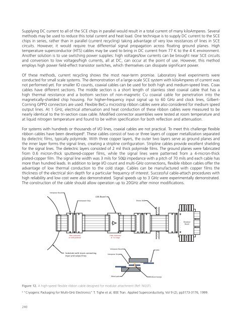
For systems with hundreds or thousands of I/O lines, coaxial cables are not practical. To meet this challenge flexible<br />
ribbon cables have been developed 8 . These cables consist of two or three layers of copper metallization separated<br />
by dielectric films, typically polyimide. With three copper layers, the outer two layers serve as ground planes and<br />
the inner layer forms the signal lines, creating a stripline configuration. Stripline cables provide excellent shielding<br />
for the signal lines. The dielectric layers consisted of 2 mil thick polyimide films. The ground planes were fabricated<br />
from 0.6 micron-thick sputtered-copper films, while the signal lines were patterned from a 4-micron-thick<br />
plated-copper film. The signal line width was 3 mils for 50Ω impedance with a pitch of 70 mils and each cable has<br />
more than hundred leads. In addition to large I/O count and multi-GHz connections, flexible ribbon cables offer the<br />
advantage of low thermal conduction to the cold stage. Cables can be manufactured with copper films the<br />
thickness of the electrical skin depth for a particular frequency of interest. Successful cable-attach procedures with<br />
high reliability and low cost were also demonstrated. Signal speeds up to 3 GHz were experimentally demonstrated.<br />
The construction of the cable should allow operation up to 20GHz after minor modifications.<br />
Interposer Board<br />
LNA Board<br />
Interposer Strip<br />
Dewar Wall<br />
Breakout<br />
Board<br />
Heat stationed<br />
at cold pedestal<br />
Heat stationed<br />
at 1st stage<br />
Substrate with traces connecting<br />
input and output lines<br />
Interposer Board<br />
Interposer Strip<br />
Cable<br />
Metal pads<br />
Indium bumps<br />
Figure 12. A high-speed flexible ribbon cable designed for modular attachment (Ref: NGST).<br />
8<br />
“Cryogenic Packaging for Multi-GHz Electronics” T. Tighe et al, IEEE Tran. Applied Superconductivity, Vol 9 (2), pp3173-3176, 1999.<br />
240