Series 04 Ku-Band TVRO Antenna
Series 04 Ku-Band TVRO Antenna
Series 04 Ku-Band TVRO Antenna

Create successful ePaper yourself
Turn your PDF publications into a flip-book with our unique Google optimized e-Paper software.
Basic System Information<br />
<strong>Series</strong> <strong>04</strong> <strong>Ku</strong>-<strong>Band</strong> <strong>TVRO</strong> <strong>Antenna</strong><br />
the satellite. The heavier the rain, the greater the signal loss. When the amount of loss is high<br />
enough, the antenna will not be able to stay locked onto the satellite signal. Once the amount of<br />
rain has decreased sufficiently, the antenna will re-acquire the satellite signal. In strong signal areas,<br />
rain fall of about four inches per hour will cause complete loss of signal. In weaker signal areas,<br />
lighter rainfall might cause the signal to be lost.<br />
3.1.2. Signal level<br />
The level of the receive signal on a point on the globe is dependant upon how powerful the<br />
transmission is and how wide the signal beam is coverage area is. Focusing the signal into a<br />
narrower beam concentrates its energy over a smaller geographic area, thereby increasing the signal<br />
level throughout that area of coverage. This makes it possible for you to use a smaller antenna size<br />
to receive that satellite signal. The antenna system must be geographically located in an area where<br />
the signal level from the satellite meets (or exceeds) the minimum satellite signal level required for<br />
your size of antenna (refer to the Specifications section of this manual) to provide suitable<br />
reception. This limits the number of satellites that can be used and the geographic areas where the<br />
ship can travel where the signal level is expected to be strong enough to continue providing<br />
uninterrupted reception. When travelling outside this minimum signal coverage area, it is normal<br />
for the system to experience an interruption in its ability to provide the desired satellite services<br />
until entering (or re-entering) an area of adequate signal level (refer to the satellite footprint<br />
information). Systems with larger diameter dish antennas can receive signal further out towards the<br />
fringe of a given satellites coverage area.<br />
3.1.3. Satellite Footprints<br />
The focused beam(s) from the satellites are normally aimed at the major land masses where there<br />
are large population centers. Footprint charts graphically display the signal level expected to be<br />
received in different geographic locations within the area of coverage. The signal will always be<br />
strongest in the center of the coverage area and weaker out toward the outer edges of the pattern.<br />
The Drawing section of this manual contains footprint charts of satellites that are expected to<br />
provide adequate signal level for your size antenna. The coverage areas are intended to be a guide<br />
to reception, however, the actual coverage area and signal level and vary. Also the signal strength is<br />
affected by weather.<br />
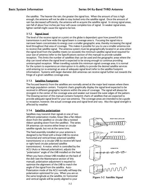
3.1.4. Satellite polarization<br />
Satellites may transmit their signals in one of two<br />
different polarization modes, linear (like a flat ribbon<br />
down from the satellite) or circular (like a twisted<br />
ribbon spiraling down from the satellite). The series<br />
<strong>04</strong> antennas can receive either linear or circular<br />
satellite signals, but not at the same time.<br />
The feed assembly installed on your antenna is<br />
designed to be fitted with a linear LNB (to receive<br />
horizontal and vertical linear polarized satellite<br />
transmissions) or a circular LNB (to receive left hand<br />
or right hand circular polarized satellite<br />
transmissions). A motor, which is controlled by the<br />
ACU (Auto or Manual polarization), adjusts the<br />
“polarization” angle of the LNB installed on the feed.<br />
When you have a linear LNB installed on the back of<br />
the dish (see the Maintenance section of this<br />
manual), polarization adjustment is required to<br />
optimize the alignment of the LNB to match the<br />
angle of the signal from the satellite. Auto-<br />
Polarization mode of the ACU normally will keep the<br />
polarization optimized for you. When you are on<br />
the same longitude as the satellite, its’ horizontal<br />
and vertical signals will be purely aligned to your<br />
Figure 3-2 Satellite Signal<br />
3-2

![NC1147 (pdf 1.47 mb) Nitrogen Concentrator [OBIGGS] - Cobham plc](https://img.yumpu.com/51124104/1/190x245/nc1147-pdf-147-mb-nitrogen-concentrator-obiggs-cobham-plc.jpg?quality=85)