Series 04 Ku-Band TVRO Antenna
Series 04 Ku-Band TVRO Antenna
Series 04 Ku-Band TVRO Antenna

You also want an ePaper? Increase the reach of your titles
YUMPU automatically turns print PDFs into web optimized ePapers that Google loves.
Specifications<br />
<strong>Series</strong> <strong>04</strong> <strong>Ku</strong>-<strong>Band</strong> <strong>TVRO</strong> <strong>Antenna</strong><br />
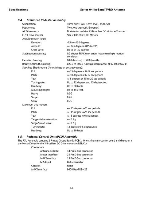
8.4. Stabilized Pedestal Assembly<br />
Stabilization:<br />
Three axis: Train, Cross-level, and Level<br />
Positioning:<br />
Two Axis (Azimuth, Elevation)<br />
AZ Drive motor:<br />
Double stacked size 23 Brushless DC Motor w/Encoder<br />
EL/CL Drive motors:<br />
Size 23 Brushless DC Motors<br />
Angular motion range:<br />
Elevation:<br />
-15 to +120 degrees<br />
Azimuth: +/- 345 degrees (015 to 705)<br />
Cross-Level:<br />
Up to +/- 30 degrees<br />
Stabilization Accuracy<br />
0.2 degree PEAK error under maximum ship's motion<br />
condition<br />
Elevation Pointing<br />
00.0 (horizon) to 90.0 (zenith)<br />
Relative Azimuth Pointing: 020.0 to 700.0 (Unwrap should occur at 023.0 or 697.0)<br />
Specified Ship Motions (for stabilization accuracy tests):<br />
Roll:<br />
+/-15 degrees at 8-12 sec periods<br />
Pitch:<br />
+/-10 degrees at 6-12 sec periods<br />
Yaw:<br />
+/-8 degrees at 15 to 20 sec periods<br />
Turning rate:<br />
Up to 12 deg/sec and 15 deg/sec/sec<br />
Headway:<br />
Up to 50 knots<br />
Mounting height:<br />
Up to 150 feet.<br />
Heave 0.5G<br />
Surge 0.2G<br />
Sway 0.2G<br />
Maximum ship motion:<br />
Roll:<br />
+/- 25 degrees w/6 sec periods<br />
Pitch:<br />
+/- 15 degrees w/6 sec periods<br />
Yaw:<br />
+/- 8 degrees w/6 sec periods<br />
Tangential Acceleration: +/- 0.5 g<br />
Surge/Sway/Heave:<br />
+/- 0.2 g<br />
Turning rate:<br />
12 deg/sec @ 5 deg/sec/sec<br />
Headway:<br />
Up to 30 knots<br />
8.5. Pedestal Control Unit (PCU) Assembly<br />
The PCU Assembly contains 2 Printed Circuit Boards (PCBs). One is the main control board and the other is<br />
the Motor Driver for the 3 Brushless DC Drive motors (AZ/EL/CL).<br />
Connectors<br />
<strong>Antenna</strong> Pedestal 44 Pin D-Sub connector<br />
Motor Interface 25 Pin D-Sub connector<br />
M&C Interface 15 Pin D-Sub connector<br />
GPS Input<br />
BNC connector<br />
Controls<br />
None<br />
M&C Interface<br />
9600 Baud RS-422<br />
8-2
![NC1147 (pdf 1.47 mb) Nitrogen Concentrator [OBIGGS] - Cobham plc](https://img.yumpu.com/51124104/1/190x245/nc1147-pdf-147-mb-nitrogen-concentrator-obiggs-cobham-plc.jpg?quality=85)