Series 04 Ku-Band TVRO Antenna
Series 04 Ku-Band TVRO Antenna
Series 04 Ku-Band TVRO Antenna

Create successful ePaper yourself
Turn your PDF publications into a flip-book with our unique Google optimized e-Paper software.
<strong>Series</strong> <strong>04</strong> <strong>Ku</strong>-<strong>Band</strong> <strong>TVRO</strong> <strong>Antenna</strong><br />
Troubleshooting and Maintenance<br />
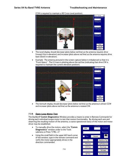
CCW is required to maintain a 90°Cross-Level position).<br />
• The Level display should decrease (plots below red line) as the antenna requires drive<br />
forward (Up in elevation) and increase (plots above red line) as the antenna requires drive<br />
back (Down in elevation).<br />
• Example: The antenna pictured in the screen capture below is imbalanced so that it is<br />
“Front Heavy”. The LV trace is plotting above the red line (indicating that drive CW is<br />
required to maintain the current elevation position).<br />
• The Azimuth display should decrease (plots below red line) as the antenna is driven CCW<br />
and increase (plots above red line) as the antenna is rotated CW.<br />
7.3.8. Open Loop Motor Test<br />
The DacRemP Comm Diagnostics Window provides a means to enter in Remote Commands for<br />
driving each individual torque motor to test that motors functionality. By driving each axis and<br />
observing the resulting motion of the antenna, a coarse operational status of the motor and motor<br />
driver may be established.<br />
• To manually drive the motors, select the “Comm<br />
Diagnostics” window under to the Tools<br />
submenu or Press “CTRL + C”<br />
• Using the small field in the upper left hand corner<br />
of the window, type in the remote command and<br />
verify the motor appropriately drives in the<br />
direction commanded.<br />
7-9
![NC1147 (pdf 1.47 mb) Nitrogen Concentrator [OBIGGS] - Cobham plc](https://img.yumpu.com/51124104/1/190x245/nc1147-pdf-147-mb-nitrogen-concentrator-obiggs-cobham-plc.jpg?quality=85)