Series 04 Ku-Band TVRO Antenna
Series 04 Ku-Band TVRO Antenna
Series 04 Ku-Band TVRO Antenna

Create successful ePaper yourself
Turn your PDF publications into a flip-book with our unique Google optimized e-Paper software.
Troubleshooting and Maintenance<br />
<strong>Series</strong> <strong>04</strong> <strong>Ku</strong>-<strong>Band</strong> <strong>TVRO</strong> <strong>Antenna</strong><br />
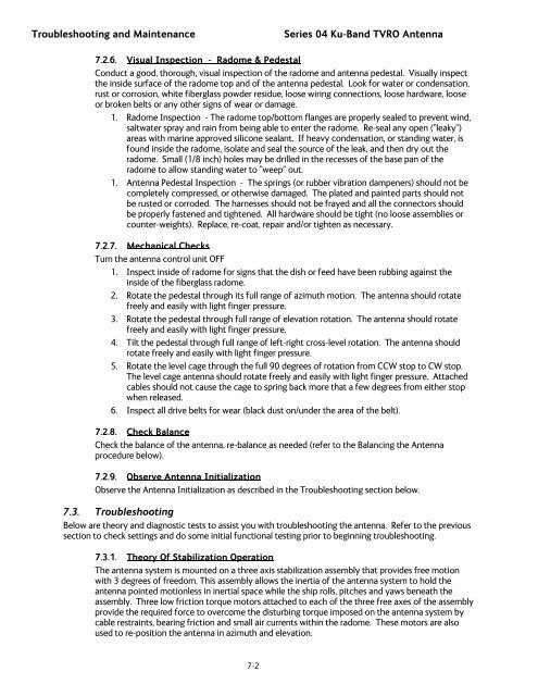
7.2.6. Visual Inspection - Radome & Pedestal<br />
Conduct a good, thorough, visual inspection of the radome and antenna pedestal. Visually inspect<br />
the inside surface of the radome top and of the antenna pedestal. Look for water or condensation,<br />
rust or corrosion, white fiberglass powder residue, loose wiring connections, loose hardware, loose<br />
or broken belts or any other signs of wear or damage.<br />
1. Radome Inspection - The radome top/bottom flanges are properly sealed to prevent wind,<br />
saltwater spray and rain from being able to enter the radome. Re-seal any open (“leaky”)<br />
areas with marine approved silicone sealant. If heavy condensation, or standing water, is<br />
found inside the radome, isolate and seal the source of the leak, and then dry out the<br />
radome. Small (1/8 inch) holes may be drilled in the recesses of the base pan of the<br />
radome to allow standing water to “weep” out.<br />
1. <strong>Antenna</strong> Pedestal Inspection - The springs (or rubber vibration dampeners) should not be<br />
completely compressed, or otherwise damaged. The plated and painted parts should not<br />
be rusted or corroded. The harnesses should not be frayed and all the connectors should<br />
be properly fastened and tightened. All hardware should be tight (no loose assemblies or<br />
counter-weights). Replace, re-coat, repair and/or tighten as necessary.<br />
7.2.7. Mechanical Checks<br />
Turn the antenna control unit OFF<br />
1. Inspect inside of radome for signs that the dish or feed have been rubbing against the<br />
inside of the fiberglass radome.<br />
2. Rotate the pedestal through its full range of azimuth motion. The antenna should rotate<br />
freely and easily with light finger pressure.<br />
3. Rotate the pedestal through full range of elevation rotation. The antenna should rotate<br />
freely and easily with light finger pressure.<br />
4. Tilt the pedestal through full range of left-right cross-level rotation. The antenna should<br />
rotate freely and easily with light finger pressure.<br />
5. Rotate the level cage through the full 90 degrees of rotation from CCW stop to CW stop.<br />
The level cage antenna should rotate freely and easily with light finger pressure. Attached<br />
cables should not cause the cage to spring back more that a few degrees from either stop<br />
when released.<br />
6. Inspect all drive belts for wear (black dust on/under the area of the belt).<br />
7.2.8. Check Balance<br />
Check the balance of the antenna, re-balance as needed (refer to the Balancing the <strong>Antenna</strong><br />
procedure below).<br />
7.2.9. Observe <strong>Antenna</strong> Initialization<br />
Observe the <strong>Antenna</strong> Initialization as described in the Troubleshooting section below.<br />
7.3. Troubleshooting<br />
Below are theory and diagnostic tests to assist you with troubleshooting the antenna. Refer to the previous<br />
section to check settings and do some initial functional testing prior to beginning troubleshooting.<br />
7.3.1. Theory Of Stabilization Operation<br />
The antenna system is mounted on a three axis stabilization assembly that provides free motion<br />
with 3 degrees of freedom. This assembly allows the inertia of the antenna system to hold the<br />
antenna pointed motionless in inertial space while the ship rolls, pitches and yaws beneath the<br />
assembly. Three low friction torque motors attached to each of the three free axes of the assembly<br />
provide the required force to overcome the disturbing torque imposed on the antenna system by<br />
cable restraints, bearing friction and small air currents within the radome. These motors are also<br />
used to re-position the antenna in azimuth and elevation.<br />
7-2
![NC1147 (pdf 1.47 mb) Nitrogen Concentrator [OBIGGS] - Cobham plc](https://img.yumpu.com/51124104/1/190x245/nc1147-pdf-147-mb-nitrogen-concentrator-obiggs-cobham-plc.jpg?quality=85)