Series 04 Ku-Band TVRO Antenna
Series 04 Ku-Band TVRO Antenna
Series 04 Ku-Band TVRO Antenna

Create successful ePaper yourself
Turn your PDF publications into a flip-book with our unique Google optimized e-Paper software.
Troubleshooting and Maintenance<br />
<strong>Series</strong> <strong>04</strong> <strong>Ku</strong>-<strong>Band</strong> <strong>TVRO</strong> <strong>Antenna</strong><br />
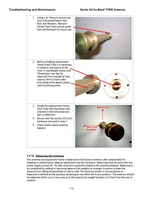
1. Using a ¼” Wrench remove the<br />
four 4-40 Small Pattern Hex<br />
Nuts and Washers. Remove<br />
Vertex Feed Tube and set aside.<br />
Save all Hardware for future use.<br />
2. Before installing replacement<br />
Vertex Feed Tube it is necessary<br />
to observe orientation of the<br />
inner ½ wavelength phase card.<br />
*Orientation can also be<br />
observed from outside of feed<br />
tube by the 4 (2 each side)<br />
protruding white plastic phase<br />
card mounting points.<br />
3. Install the replacement Vertex<br />
Feed Tube with the phase card<br />
oriented in the horizontal axis<br />
(ref. to reflector).<br />
4. Secure with the Loctite 222 and<br />
hardware removed in step 1.<br />
5. Check and/or adjust antenna<br />
balance<br />
7.4.16. Balancing the <strong>Antenna</strong><br />
The antenna and equipment frame is balanced at the factory however, after disassembly for<br />
shipping or maintenance, balance adjustment may be necessary. Balancing must be done with the<br />
power supply turned off. No belt removal is required to balance the antenna pedestal. Balancing is<br />
accomplished by adding or removing balance trim weights at strategic locations to keep the<br />
antenna from falling forward/back or side to side. The antenna system is not pendulous so<br />
'balanced' is defined as the antenna remaining at rest when left in any position. The antenna should<br />
be balanced within one or two ounces at the typical trim weight location of 2 feet from the axis of<br />
rotation.<br />
7-52
![NC1147 (pdf 1.47 mb) Nitrogen Concentrator [OBIGGS] - Cobham plc](https://img.yumpu.com/51124104/1/190x245/nc1147-pdf-147-mb-nitrogen-concentrator-obiggs-cobham-plc.jpg?quality=85)