- Page 1:
Type B Vital Relays Copyright © 19
- Page 5 and 6:
LIST OF EFFECTIVE PAGES P1457, Type
- Page 7 and 8:
PREFACE NOTICE OF CONFIDENTIAL INFO
- Page 9 and 10:
ABOUT THE MANUAL This manual is int
- Page 11 and 12:
MANUAL SPECIAL NOTATIONS In the Als
- Page 13 and 14:
Topic TABLE OF CONTENTS Page 1. SEC
- Page 15 and 16:
Topic TABLE OF CONTENTS (CONT.) Pag
- Page 17 and 18:
Description LIST OF FIGURES (CONT.)
- Page 19 and 20:
Description LIST OF TABLES Page Tab
- Page 21 and 22:
General Description 1. SECTION 1 -
- Page 23 and 24:
General Description 1.2.2. Identifi
- Page 25 and 26:
General Description 1.2.3. Relay Pr
- Page 27 and 28:
General Description 1.2.4. Mounting
- Page 29 and 30:
General Description The registratio
- Page 31 and 32:
General Description 1.2.7.2. Test T
- Page 33 and 34:
General Description 16 26 36 46 56
- Page 35 and 36:
General Description 1.2.10. Relay C
- Page 37 and 38:
Theory of Operation 2. SECTION 2 -
- Page 39 and 40:
Theory of Operation 2.2. RELAY CONT
- Page 41 and 42:
Theory of Operation 2.2.2.1. Contac
- Page 43 and 44:
Theory of Operation 2.2.2.3. Heavy-
- Page 45 and 46:
Theory of Operation 2.2.3. Coils A
- Page 47 and 48:
P1457, Rev. Nov/07 2-11 Alstom Sign
- Page 49 and 50:
Theory of Operation 2.3. BIASED-NEU
- Page 51 and 52:
Theory of Operation 2.4. DC LINE RE
- Page 53 and 54:
Theory of Operation S NO VOLTAGE N
- Page 55 and 56:
Theory of Operation R N NORMAL CONT
- Page 57 and 58:
Theory of Operation 2.4.4. Microchr
- Page 59 and 60:
Theory of Operation 2.4.4.2.2. Appl
- Page 61 and 62:
Theory of Operation Group Space- Fr
- Page 63 and 64:
Theory of Operation 2.4.4.3.1. Appl
- Page 65 and 66:
Theory of Operation 2.5. DC SPECIAL
- Page 67 and 68:
Theory of Operation (FRONT VIEW) 1E
- Page 69 and 70:
Theory of Operation 2.5.4. Switch-O
- Page 71 and 72:
Theory of Operation TRACK CIRCUIT E
- Page 73 and 74:
Theory of Operation 2.5.6. Code Rat
- Page 75 and 76:
Theory of Operation 2.5.7. Code-Fol
- Page 77 and 78:
Theory of Operation Figure 2-38. VT
- Page 79 and 80:
Theory of Operation Figure 2-41 sho
- Page 81 and 82:
Theory of Operation VANE CONTACTS P
- Page 83 and 84:
Theory of Operation EDDY CURRENT IN
- Page 85 and 86:
Theory of Operation In each snapsho
- Page 87 and 88:
Installation 3. SECTION 3 - INSTALL
- Page 89 and 90:
Installation Table 3-2. B Relay Ins
- Page 91 and 92:
Installation Table 3-2. B Relay Ins
- Page 93 and 94:
Installation Table 3-3. Microchron
- Page 95 and 96:
Installation Table 3-3. Microchron
- Page 97 and 98:
Installation Table 3-3. Microchron
- Page 99 and 100:
Installation Table 3-5. AC Microchr
- Page 101 and 102:
Installation Table 3-5. AC Microchr
- Page 103 and 104:
Preventive Maintenance 4. SECTION 4
- Page 105 and 106:
Preventive Maintenance 4.3. PREVENT
- Page 107 and 108:
Preventive Maintenance Table 4-2. T
- Page 109 and 110: Preventive Maintenance Table 4-3. V
- Page 111 and 112: Preventive Maintenance 4.5. ELECTRI
- Page 113 and 114: Preventive Maintenance 4.5.1. AC Li
- Page 115 and 116: Preventive Maintenance 4.5.3. Biase
- Page 117 and 118: Preventive Maintenance 4.5.5. Code
- Page 119 and 120: Preventive Maintenance 4.5.7. Micro
- Page 121 and 122: Preventive Maintenance 4.5.9. Polar
- Page 123 and 124: Preventive Maintenance 4.5.11. Swit
- Page 125 and 126: Troubleshooting 5. SECTION 5 - TROU
- Page 127 and 128: Troubleshooting Table 5-1. Troubles
- Page 129 and 130: Troubleshooting DC RELAY DOES NOT R
- Page 131 and 132: Troubleshooting AC VANE RELAY DOES
- Page 133 and 134: Troubleshooting MICROCHRON II TIMER
- Page 135 and 136: Corrective Maintenance 6. SECTION 6
- Page 137 and 138: Corrective Maintenance Table 6-2. B
- Page 139 and 140: Corrective Maintenance Table 6-2. B
- Page 141 and 142: Corrective Maintenance Table 6-4. T
- Page 143 and 144: Corrective Maintenance NOTE For det
- Page 145 and 146: Corrective Maintenance 6.4.4. Curre
- Page 147 and 148: Corrective Maintenance 6.5. MECHANI
- Page 149 and 150: Corrective Maintenance Table 6-10.
- Page 151 and 152: Corrective Maintenance 6.5.2. Mecha
- Page 153 and 154: Corrective Maintenance Table 6-11.
- Page 155 and 156: Corrective Maintenance Table 6-11.
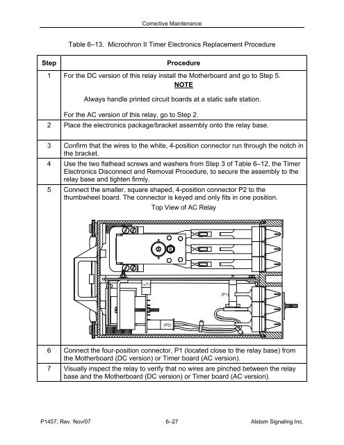
- Page 157 and 158: Corrective Maintenance 6.5.3. Micro
- Page 159: Corrective Maintenance Table 6-12.
- Page 163 and 164: Parts Catalog 7. SECTION 7 - PARTS
- Page 165 and 166: Parts Catalog 7.4. B1 BIASED-NEUTRA
- Page 167 and 168: Parts Catalog Table 7-2. B1 Neutral
- Page 169 and 170: Parts Catalog 7.5. B1 CODE-RESPONSI
- Page 171 and 172: Parts Catalog 46F Figure 7-3. B1 Co
- Page 173 and 174: Parts Catalog Table 7-3. B1 Code-Re
- Page 175 and 176: Parts Catalog Table 7-3. B1 Code-Re
- Page 177 and 178: Parts Catalog 7.7. B1 ELECTRONICALL
- Page 179 and 180: Parts Catalog Table 7-4. B1 Slow Pi
- Page 181 and 182: Parts Catalog Table 7-5. B2 Neutral
- Page 183 and 184: Parts Catalog 7.9. B2 BIASED-NEUTRA
- Page 185 and 186: Parts Catalog Table 7-6. B2 Biased-
- Page 187 and 188: Parts Catalog Table 7-7. B2 Vane Re
- Page 189 and 190: Parts Catalog 7.11. B2 AC VANE RELA
- Page 191 and 192: Parts Catalog Table 7-8. B2 Vane Re
- Page 193 and 194: Parts Catalog Figure 7-10. B2 Code
- Page 195 and 196: Parts Catalog Table 7-9. B2 Code Ra
- Page 197 and 198: Parts Catalog Table 7-9. B2 Code Ra
- Page 199 and 200: Parts Catalog FRONT VIEW 1 2 3 4 5
- Page 201 and 202: Parts Catalog Table 7-10. B2 Microc
- Page 203 and 204: Parts Catalog 7.14. B2 AC MICROCHRO
- Page 205 and 206: Parts Catalog Table 7-11. B2 AC Mic
- Page 207 and 208: Parts Catalog 7.15. TYPE VTB POLAR-
- Page 209 and 210: Parts Catalog Table 7-12. VTB Polar
- Page 211 and 212:
Parts Catalog Table 7-12. VTB Polar
- Page 213 and 214:
P1457, Rev. Nov/07 7-51 Alstom Sign
- Page 215 and 216:
P1457, Rev. Nov/07 7-53 Alstom Sign
- Page 217 and 218:
Parts Catalog MARKED END OF MAGNET
- Page 219 and 220:
Parts Catalog NOTE 1 When ordering
- Page 221 and 222:
Parts Catalog , 3B 31 E 25A 25B 30
- Page 223 and 224:
Parts Catalog Table 7-16. B Relay P
- Page 225 and 226:
Parts Catalog Table 7-16. B Relay P
- Page 227 and 228:
Parts Catalog 7.18. B RELAY REGISTR
- Page 229 and 230:
Parts Catalog Table 7-17. B Relay R
- Page 231 and 232:
Relay Engineering Data (ED) sheet L
- Page 233 and 234:
Relay Engineering Data (ED) sheet L
- Page 235 and 236:
Relay Engineering Data (ED) sheet L
- Page 237 and 238:
Relay Engineering Data (ED) sheet L
- Page 239 and 240:
Relay Engineering Data (ED) sheet L
- Page 241 and 242:
Relay Engineering Data (ED) sheet L
- Page 243 and 244:
Relay Engineering Data (ED) sheet L
- Page 245 and 246:
Relay Engineering Data (ED) sheet L
- Page 247 and 248:
Glossary B. APPENDIX B - GLOSSARY B
- Page 249 and 250:
Glossary Overpressure - • Dead We
- Page 251 and 252:
Tools and Kits C. APPENDIX C - TOOL
- Page 253 and 254:
Tools and Kits 1 A B AAR CRIMP TOOL
- Page 255 and 256:
Tools and Kits C.3. SHOP TEST RACK
- Page 257 and 258:
Tools and Kits The vane relay test
- Page 260:
FOR QUESTIONS AND INQUIRIES, CONTAC