HYDROGEL MATERIALS FOR TWO-PHOTON MICROFABRICATIONThe SEM image was obtained by using two-photon micr<strong>of</strong>abrication.The following parameters were used: laser scanspeed: 20 μm/s; 60 mW; λ= 730nm; 1 %wt <strong>of</strong> dye #41, compositionC. A porous 3D grid (stack <strong>of</strong> logs) was intended. Dye #41was used because it has large photon cross sections, and has beenobserved to polymerize acrylate systems. The fabricated structureappears highly deformed, which could be due to inadequatecrosslinking or laser induced deformations.CONCLUSIONSufficient crosslinking can be achieved by UV exposure.It was found that setup 1 was the most effective in the UV exposureexperiments. From the different compositions that weretested, composition C (1:2:1 ratio <strong>of</strong> EGMA:VP:HEMA) gavethe most crosslinking per exposure. In later experiments usingthe UV mask, composition C with a 1wt% <strong>of</strong> UV #7 was used.No change in width was observed. This may have been due to alarge amount <strong>of</strong> crosslinking within the structure. At high crosslinking,the swelling <strong>of</strong> a structure in the presence <strong>of</strong> water maybe limited. In the bulk specimen, the thickness <strong>of</strong> the samplesshowed a large change relative to the diameter. The small changemay result in the lack <strong>of</strong> the sample’s ability to expand, as a largearea adheres strongly to the substrate. This may also explain thelack <strong>of</strong> change in width for the features produced lithographically.It will be useful explore a method that allows measurement<strong>of</strong> the height <strong>of</strong> the fabricated features. This work shows thathydrophilic monomers can be crosslinked using UV initiators andcurrent two-photon absorbing dyes (#41). However, other dyesshould be investigated for higher efficiency. Future work willinvolve investigating more efficient two-photon absorbing dyes,find other biocompatible materials, write functional microstructures,and characterize the swelling ratios in more detail.ACKNOWLEDGEMENTSDept. <strong>of</strong> Chemistry and Biochemistry at the Georgia Institute <strong>of</strong>TechnologyMDITR REUNational Science FoundationDr. Joe PerryDr. Mariacristina RumiVincent ChenWojtek HaskeKelly PerryPerry GroupDr. Keith OdenMs. Olanda BryantBeverly ScheererFor me, understanding the physical forces in life mean understandingscience. Norfolk State <strong>University</strong> and Georgia Institute <strong>of</strong>Technology have afforded me many opportunities to do so.REFERENCES(1) Zhou, W.; Kuebler, S.M.; Braun, K.L.; Yu, T.; Cammack,J.K.; Ober, C.K.; Perry, J.W.; Marder, S.R. Science, 2002, 296,1106-1109(2) Watanabe, T; Akiyama, M.; Totani, K.; Kuebler, S.M.; Stellacci,F.; Wenseleers, W.; Braun, K.; Marder, S.R.; Perry, J.W.Adv. Funct. Mater., 2002, 12, 611-614(3) Cumpston, B; Sundaravel, A.P; Barlow, S; Dyer, D.; Ehrlich,J.; Erskine, L.L; Heikal, A.; Kuebler, S.; Lee, S.; McCord-Maughon, D.; Qin, J.; Röckel, H.; Rumi, M.; Wu, X.; Marder, S.;Perry, J. Nature, 1999, 398, 51-54126 CMDITR Review <strong>of</strong> Undergraduate Research Vol. 2 No. 1 Summer <strong>2005</strong>
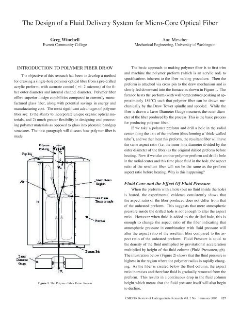
The Design <strong>of</strong> a Fluid Delivery System for Micro-Core Optical FiberGreg WinchellEverett Community CollegeAnn MescherMechanical Engineering, <strong>University</strong> <strong>of</strong> <strong>Washington</strong>INTRODUCTION TO POLYMER FIBER DRAWThe objective <strong>of</strong> this research has been to develop a methodfor drawing a single-hole polymer optical fiber from a pre-drilledacrylic preform, with accurate control ( +/- 2 microns) <strong>of</strong> the fiberouter diameter and internal channel diameter. Polymer fiber<strong>of</strong>fers superior design capabilities compared to currently manufacturedglass fiber, along with potential savings in energy andmanufacturing cost. The most significant advantages <strong>of</strong> polymerfiber are: 1) the ability to incorporate unique organic optical materials,and 2) much greater flexibility in designing and processingpolymer materials as opposed to glass into photonic bandgapstructures. The next paragraph will discuss how polymer fiber ismade.The basic approach to making polymer fiber is to first trimand machine the polymer preform (which is an acrylic rod) tospecifications inherent to the fiber making procedure. Then thepreform is attached via cross pin to the draw mechanism and isslowly fed downward into the furnace as shown in Figure 1. Thefurnace heats the preform (with wall temperatures peaking at approximately184°C) such that polymer fiber can be drawn mechanicallyby the Draw Tower spindle and spooled. While thefiber is drawn a Laser Diameter Gauge measures the outer diameter<strong>of</strong> the fiber produced by the process. This is the basic processfor producing polymer fiber.If we take a polymer preform and drill a hole in the radialcenter along the axis <strong>of</strong> the preform (thus forming a “thick-walledtube”), and we then heat this preform, the resultant fiber will havethe same aspect ratio (i.e. the inner hole diameter divided by theouter diameter <strong>of</strong> the fiber) as the original drilled preform beforeheating. Now if we take another polymer preform and drill a holein the radial center and this time place fluid in the hole, the aspectratio <strong>of</strong> the resultant fiber will not be the same as the preformaspect ratio before heating. Why is this happening?Figure 1. The Polymer Fiber Draw ProcessFluid Core and the Effect Of Fluid PressureWhen the preform with a hole (but no fluid inside the hole)is heated, the experimental evidence consistently shows thatthe aspect ratio <strong>of</strong> the fiber produced does not differ from that<strong>of</strong> the unheated preform. This suggests that mere atmosphericpressure inside the drilled hole is not enough to alter the aspectratio. However when fluid is added to the drilled hole, this isenough to change the aspect ratio <strong>of</strong> the fiber indicating thatatmospheric pressure in combination with fluid pressure willalter the aspect ratio <strong>of</strong> the resultant fiber compared to the aspectratio <strong>of</strong> the unheated preform. Fluid Pressure is equal tothe density <strong>of</strong> the fluid multiplied by gravitational accelerationmultiplied by height <strong>of</strong> the fluid column (Fluid Pressure=ρgh).The illustration below (Figure 2) shows that the fluid pressure ishighest in the region where the polymer radius is rapidly changing.As the fiber is created below the fluid column, the aspectratio increases and therefore fluid is gradually removed from thepreform. This results in a continuous drop in the fluid columnheight which means that the fluid pressure itself will also beginto decline.CMDITR Review <strong>of</strong> Undergraduate Research Vol. 2 No. 1 Summer <strong>2005</strong> 127
- Page 2 and 3:
The material is based upon work sup
- Page 4 and 5:
TABLE OF CONTENTSSynthesis of Dendr
- Page 6 and 7:
6 CMDITR Review of Undergraduate Re
- Page 8 and 9:
SYNTHESIS OF DENDRIMER BUILDING BLO
- Page 10 and 11:
throughout the work period. Five su
- Page 12 and 13:
12 CMDITR Review of Undergraduate R
- Page 14 and 15:
BARIUM TITANATE DOPED SOL-GEL FOR E
- Page 16 and 17:
BARIUM TITANATE DOPED SOL-GEL FOR E
- Page 18 and 19:
SYNTHESIS OF NORBORNENE MONOMER OF
- Page 20:
20 CMDITR Review of Undergraduate R
- Page 23 and 24:
using different reaction conditions
- Page 25 and 26:
Synthesis of Nonlinear Optical-Acti
- Page 27 and 28:
quality of the XRD structures wasca
- Page 29 and 30:
Behavioral Properties of Colloidal
- Page 32 and 33:
Transmission electron microscopy ha
- Page 34 and 35:
34 CMDITR Review of Undergraduate R
- Page 36 and 37:
areorient themselves with the elect
- Page 38 and 39:
Fabry-Perot modulators with electro
- Page 40 and 41:
40 CMDITR Review of Undergraduate R
- Page 42 and 43:
QUANTIZED HAMILTON DYNAMICS APPLIED
- Page 44 and 45:
44 CMDITR Review of Undergraduate R
- Page 46 and 47:
INVESTIGATING NEW CLADDING AND CORE
- Page 48 and 49:
Dr. Robert NorwoodChris DeRoseAmir
- Page 50 and 51:
SYNTHESIS OF TPD-BASED COMPOUNDS FO
- Page 52 and 53:
SYNTHESIS OF TPD-BASED COMPOUNDS FO
- Page 54 and 55:
OPTIMIZING HYBRID WAVEGUIDESpropaga
- Page 56 and 57:
At closer spaces the second undesir
- Page 58 and 59:
SYNTHESIS AND ANALYSIS OF THIOL-STA
- Page 60 and 61:
60 CMDITR Review of Undergraduate R
- Page 62 and 63:
QUINOXALINE-CONTAINING POLYFLUORENE
- Page 64 and 65:
QUINOXALINE-CONTAINING POLYFLUORENE
- Page 66 and 67:
66 CMDITR Review of Undergraduate R
- Page 68 and 69:
SYNTHESIS OF DENDRON-FUNCTIONALIZED
- Page 70 and 71:
70 CMDITR Review of Undergraduate R
- Page 72 and 73:
BUILDING AN OPTICAL OXIMETER TO MEA
- Page 74 and 75:
74 CMDITR Review of Undergraduate R
- Page 76 and 77: 76 CMDITR Review of Undergraduate R
- Page 78 and 79: TOWARD MOLECULAR RESOLUTION C-AFM W
- Page 80 and 81: TOWARD MOLECULAR RESOLUTION C-AFM W
- Page 82 and 83: SYNTHESIS AND CHARACTERIZATION OF E
- Page 84 and 85: My name is Aaron Montgomery and I a
- Page 86 and 87: 1,1-DIPHENYL-2,3,4,5-TETRAKIS(9,9-D
- Page 88 and 89: 1,1-DIPHENYL-2,3,4,5-TETRAKIS(9,9-D
- Page 90 and 91: EFFECTS OF SURFACE CHEMISTRY ON CAD
- Page 92 and 93: EFFECTS OF SURFACE CHEMISTRY ON CAD
- Page 94 and 95: 94 CMDITR Review of Undergraduate R
- Page 96 and 97: SYNTHESIS OF A POLYENE EO CHROMOPHO
- Page 98 and 99: SYNTHESIS OF A POLYENE EO CHROMOPHO
- Page 102 and 103: 102 CMDITR Review of Undergraduate
- Page 104 and 105: CHARACTERIZATION OF THE MOLECULAR P
- Page 106 and 107: 106 CMDITR Review of Undergraduate
- Page 108 and 109: OPTIMIZATION OF SEMICONDUCTOR NANOP
- Page 110 and 111: OPTIMIZATION OF SEMICONDUCTOR NANOP
- Page 112 and 113: CHARACTERIZATION OF THE PHOTODECOMP
- Page 114 and 115: 114 CMDITR Review of Undergraduate
- Page 116 and 117: ELECTROLUMINESCENT PROPERTIES OF OR
- Page 118 and 119: 118 CMDITR Review of Undergraduate
- Page 120 and 121: DETERMINATION OF MOLECULAR ORIENTAT
- Page 122 and 123: DETERMINATION OF MOLECULAR ORIENTAT
- Page 124 and 125: HYDROGEL MATERIALS FOR TWO-PHOTON M
- Page 128 and 129: THE DESIGN OF A FLUID DELIVERY SYST
- Page 130: THE DESIGN OF A FLUID DELIVERY SYST