Student Project Abstracts 2005 - Pluto - University of Washington
Student Project Abstracts 2005 - Pluto - University of Washington
Student Project Abstracts 2005 - Pluto - University of Washington

You also want an ePaper? Increase the reach of your titles
YUMPU automatically turns print PDFs into web optimized ePapers that Google loves.
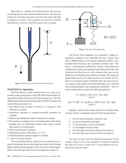
THE DESIGN OF A FLUID DELIVERY SYSTEM FOR MICRO-CORE OPTICAL FIBERSince there is a decline in the fluid pressure, the pressureexerted against the inner diameter hole decreases. The decreasein pressure will reduce the aspect ratio over time unless the fluidis replaced as needed. This engenders the need for a reliablefluid delivery system to control the aspect ratio as needed.Figure 3. The Gravity Feed ApparatusFigure 2. Fluid Pressure in Preform due to Fluid ColumnFluid Delivery ApparatusThe fluid delivery system considered first was a type <strong>of</strong> automatedsyringe pump known as the NE-1000 Programmable SyringePump retailed by the New Era Pump Systems, Inc. The NE-1000 Programmable Syringe Pump retails for $995 US Dollars andhas the following features [1]:1. The infusion rates are from 0.73 μl/hr (1 cc syringe) to 2100ml/hr (60 cc syringe).2. Stand-alone operation or computer-controlled operation areavailable.3. Infusion and withdrawal <strong>of</strong> fluid is performed as needed.4. The operator can program up to 41 pumping phases that changepumping rates, set dispensing volumes, insert pauses, controland respond to external signals.5. Motor stall detection is included.6. Dispensing accuracy <strong>of</strong> the device is +/- 1%7. Unlimited lifetime technical support is available.8. It has a two-year warranty.The second fluid delivery system that was considered was agravity feed design that was developed and tested in the PolymerOptics and Processing Laboratory at the <strong>University</strong> <strong>of</strong> <strong>Washington</strong>.Below is the drawing <strong>of</strong> the Gravity Feed Apparatus (Figure 3):The Gravity Feed Apparatus was essentially a siphon arrangementcomposed <strong>of</strong> an adjustable lab jack, a plastic flowtube, a 2000ml beaker, a 1ml capacity graduated cylinder, a topmountedfluid feed ramp, and a graduated cylinder stand. Thisdevice demonstrated excellent flow control. Under laboratoryconditions the single most important factor affecting the flow rate<strong>of</strong> the fluid with this device (i.e. the volumetric flow rate) was thedifference in the height <strong>of</strong> the collection container (Z2) minus theheight <strong>of</strong> the reservoir (Z1) otherwise known as ΔZ (ΔZ= Z2-Z1).However to properly predict volumetric flow rates from this devicerequires math models from Fluid Mechanics [3], combinedwith an understanding <strong>of</strong> the components <strong>of</strong> fluid flow. Thus weneed to understand and utilize the following equations:V = [D2 g / (32 ν L)] * (h + ∆Z)equation 1Q = V π D 2 / 4 = [π D 4 g / (128 ν L)] * (h + ΔZ)equation 2Equation 1 refers to the average velocity (V) in the flow tube.Average velocity is dependent upon the following parameters:1. D is the internal diameter <strong>of</strong> the flow tube.2. g is the gravitational acceleration.3. ν is the kinematic viscosity <strong>of</strong> the fluid.4. L is the length <strong>of</strong> the flow tube.5. h is the height <strong>of</strong> the fluid column in the reservoir.6. ΔZ is the difference between Z2-Z1 (see Figure 3)Now that we have noted the important parameters for theaverage velocity V, we can use equation 2 to find the volumetricflow rate Q = V π D 2 / 4, where π D 2 / 4 is the internal cross-sectionalarea <strong>of</strong> the flow tube.128 CMDITR Review <strong>of</strong> Undergraduate Research Vol. 2 No. 1 Summer <strong>2005</strong>