Student Project Abstracts 2005 - Pluto - University of Washington
Student Project Abstracts 2005 - Pluto - University of Washington
Student Project Abstracts 2005 - Pluto - University of Washington

Create successful ePaper yourself
Turn your PDF publications into a flip-book with our unique Google optimized e-Paper software.
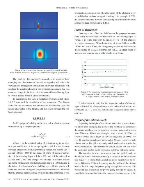
OPTIMIZING HYBRID WAVEGUIDESpropagation constants; one when the index <strong>of</strong> the cladding layeris unshifted or without an applied voltage (for example 1.202),the other is when the index <strong>of</strong> the cladding layer is shifted due anapplied voltage (for example 1.200).Index <strong>of</strong> RefractionLooking at the effect the shift has on the propagation constantwhen the base index <strong>of</strong> refraction <strong>of</strong> the cladding layer isvaried, it is found that over the range <strong>of</strong> 1 to 1.5 the changesis relatively constant. With dimensions <strong>of</strong> height 200nm, width180nm and space 50nm, the change only varies by 6m -1 over anindex change <strong>of</strong> 0.03, as illustrated in Fig. 3. A larger range <strong>of</strong>indexes was sampled and similar results were found.Figure 2. Top: A power flow diagram <strong>of</strong> a hybrid waveguide’s guidedmode. Bottom: Power flow diagram <strong>of</strong> a traditional waveguide guided mode.The goal for this summer’s research is to discover howchanging the dimensions <strong>of</strong> hybrid waveguides will affect thewaveguide’s propagation constant and also what dimensions willproduce the greatest change in the propagation constant due to aconstant change in the index <strong>of</strong> refraction without allowing lightto form a guided mode in the silicon blocks.To accomplish this task, a modeling program called FEM-LAB 3 was used for simulation <strong>of</strong> the structures. The dimensionsthat can be changed are: the index <strong>of</strong> the cladding layer, theheight and width <strong>of</strong> the blocks, and the space between the twoblocks (space).RESULTSAn EO polymer’s ability to alter the index <strong>of</strong> refraction canbe modeled by a simple equation: 3 (1)Where n is the original index <strong>of</strong> refraction, r 33is an electro-opticcoefficient, V is voltage applied, and d is the distancebetween electrodes. Using appropriate values, the typical Δn isaround -.002 to -.003. In this paper all shifts <strong>of</strong> index <strong>of</strong> refraction<strong>of</strong> the cladding layer will be -.002, and will be referred toas “the shift”, and “the change” or “change” will refer to howmuch the propagation constant changes due to a -.002 change inthe index <strong>of</strong> refraction <strong>of</strong> the cladding layer. All the graphs willshow the absolute change <strong>of</strong> the propagation constant. Also notethat the graphed data is derived from finding the difference <strong>of</strong> twoFigure 3. The amount the propagation constant changes with a -.002 change <strong>of</strong> the index <strong>of</strong> the cladding layer. Data observedat height: 200nm, width: 180nm, and space: 50nm.It is important to note that the larger the index <strong>of</strong> claddinglayer will result in a larger change in the index <strong>of</strong> refraction, accordingto Eq. (1). This was not taken in to account in the aboveanalysis.Height <strong>of</strong> the Silicon BlocksAdjusting the height <strong>of</strong> the silicon blocks has a much differenteffect than changing the index <strong>of</strong> the cladding. To determinethe maximum change in propagation constant, a range <strong>of</strong> heightsfrom 200nm to 390nm were sampled with a width <strong>of</strong> 200nm, aspace <strong>of</strong> 50nm, and a index <strong>of</strong> the cladding layer <strong>of</strong> 1.002 (seeFig. 4). A maximum change was found at 370nm. However, withsilicon blocks this tall, a second guided mode exists within theblocks themselves. The shorter the silicon blocks are, the morethe undesired guided mode becomes a substrate radiation mode.The question then becomes, when does the guided mode inthe silicon blocks become primarily a substrate radiation mode(see Fig. 5)? It seems that a useful range for heights will be between160nm to 270nm depending on the width <strong>of</strong> the siliconblocks. In this range the power going through the substrate willbe around half as much as the power going through the space. Itshould also be noted that since the range <strong>of</strong> effective heights is far54 CMDITR Review <strong>of</strong> Undergraduate Research Vol. 2 No. 1 Summer <strong>2005</strong>