Student Project Abstracts 2005 - Pluto - University of Washington
Student Project Abstracts 2005 - Pluto - University of Washington
Student Project Abstracts 2005 - Pluto - University of Washington

Create successful ePaper yourself
Turn your PDF publications into a flip-book with our unique Google optimized e-Paper software.
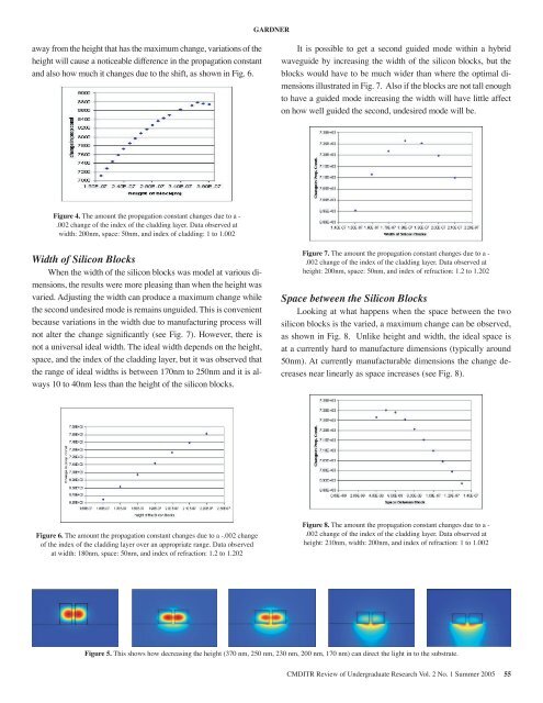
GARDNERaway from the height that has the maximum change, variations <strong>of</strong> theheight will cause a noticeable difference in the propagation constantand also how much it changes due to the shift, as shown in Fig. 6.It is possible to get a second guided mode within a hybridwaveguide by increasing the width <strong>of</strong> the silicon blocks, but theblocks would have to be much wider than where the optimal dimensionsillustrated in Fig. 7. Also if the blocks are not tall enoughto have a guided mode increasing the width will have little affecton how well guided the second, undesired mode will be.Figure 4. The amount the propagation constant changes due to a -.002 change <strong>of</strong> the index <strong>of</strong> the cladding layer. Data observed atwidth: 200nm, space: 50nm, and index <strong>of</strong> cladding: 1 to 1.002Width <strong>of</strong> Silicon BlocksWhen the width <strong>of</strong> the silicon blocks was model at various dimensions,the results were more pleasing than when the height wasvaried. Adjusting the width can produce a maximum change whilethe second undesired mode is remains unguided. This is convenientbecause variations in the width due to manufacturing process willnot alter the change significantly (see Fig. 7). However, there isnot a universal ideal width. The ideal width depends on the height,space, and the index <strong>of</strong> the cladding layer, but it was observed thatthe range <strong>of</strong> ideal widths is between 170nm to 250nm and it is always10 to 40nm less than the height <strong>of</strong> the silicon blocks.Figure 7. The amount the propagation constant changes due to a -.002 change <strong>of</strong> the index <strong>of</strong> the cladding layer. Data observed atheight: 200nm, space: 50nm, and index <strong>of</strong> refraction: 1.2 to 1.202Space between the Silicon BlocksLooking at what happens when the space between the twosilicon blocks is the varied, a maximum change can be observed,as shown in Fig. 8. Unlike height and width, the ideal space isat a currently hard to manufacture dimensions (typically around50nm). At currently manufacturable dimensions the change decreasesnear linearly as space increases (see Fig. 8).Figure 6. The amount the propagation constant changes due to a -.002 change<strong>of</strong> the index <strong>of</strong> the cladding layer over an appropriate range. Data observedat width: 180nm, space: 50nm, and index <strong>of</strong> refraction: 1.2 to 1.202Figure 8. The amount the propagation constant changes due to a -.002 change <strong>of</strong> the index <strong>of</strong> the cladding layer. Data observed atheight: 210nm, width: 200nm, and index <strong>of</strong> refraction: 1 to 1.002Figure 5. This shows how decreasing the height (370 nm, 250 nm, 230 nm, 200 nm, 170 nm) can direct the light in to the substrate.CMDITR Review <strong>of</strong> Undergraduate Research Vol. 2 No. 1 Summer <strong>2005</strong> 55