User's Manual - Pixord
User's Manual - Pixord
User's Manual - Pixord
- No tags were found...

Create successful ePaper yourself
Turn your PDF publications into a flip-book with our unique Google optimized e-Paper software.
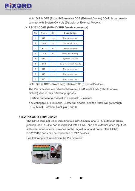
Note: DIR is DTE (<strong>Pixord</strong> IVS) relative DCE (External Device) COM1 is purpose toconnect with System Console (Default), or External Modem.‣ RS-232 COM2 (9 Pin D-SUB female connector)Pin Name Dir Description1 NC ... No connection2 TXD → Transmit Data3 RXD ← Receive Data4 DSR ← Data Set Ready5 GND — System Ground6 DTR → Data Terminal Ready7 NC ... No connection8 NC ... No connection9 NC ... No connectionNote: DIR is DCE (<strong>Pixord</strong> IVS) relative DTE (External Device).The Pin directions are different between COM1 and COM2 (refer to abovePicture), due to their different purposes.COM2 is purpose to connect to external PTZ camera.If selecting to RS-485 mode, COM2 will disable, and the traffic will go throughRS-485 in IO Terminal block pin 2 and 3.6.5.2 PiXORD 120/126/128The GPIO Terminal Block including four GPIO inputs, one GPIO output as Relayjunction, one RS-485 port multiplexed with COM2, and one external video input foradditional video source, provides control signal input and output. The COM2RS-232/485 ports can be connected to PTZ devices.See following picture indicate the Pin direction:60 / 88