User's Manual - Pixord
User's Manual - Pixord
User's Manual - Pixord
- No tags were found...

Create successful ePaper yourself
Turn your PDF publications into a flip-book with our unique Google optimized e-Paper software.
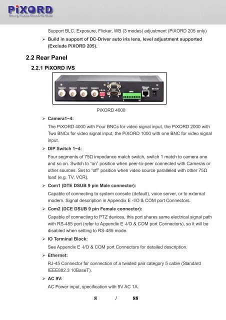
Support BLC, Exposure, Flicker, WB (3 modes) adjustment (PiXORD 205 only)‣ Build in support of DC-Driver auto iris lens, level adjustment supported(Exclude PiXORD 205).2.2 Rear Panel2.2.1 PiXORD IVSPiXORD 4000‣ Camera1~4:The PiXORD 4000 with Four BNCs for video signal input, the PiXORD 2000 withTwo BNCs for video signal input, the PiXORD 1000 with one BNC for video signalinput.‣ DIP Switch 1~4:Four segments of 75Ω impedance match switch, switch 1 match to camera oneand so on. Switch to “on” position when peer-to-peer connected with Cameras orother sources. Set to “off” position when video source paralleled with other 75Ωload (e.g. TV, VCR).‣ Com1 (DTE DSUB 9 pin Male connector):Capable of connecting to system console (default), voice server, or to externalmodem. Signal description in Appendix E -I/O & COM port Connectors.‣ Com2 (DCE DSUB 9 pin Female connector):Capable of connecting to PTZ devices, this port shares same electrical signal pathwith RS-485 port (refer to Appendix E -I/O & COM port Connectors), so it will bedisabled when setting to RS-485 mode.‣ IO Terminal Block:See Appendix E -I/O & COM port Connectors for detailed description.‣ Ethernet:RJ-45 Connector for connection of a twisted pair category 5 cable (StandardIEEE802.3 10BaseT).‣ AC 9V:AC Power input, specification with 9V AC 1A.8 / 88