Setup and Reference Guide - Kollmorgen
Setup and Reference Guide - Kollmorgen
Setup and Reference Guide - Kollmorgen

Create successful ePaper yourself
Turn your PDF publications into a flip-book with our unique Google optimized e-Paper software.
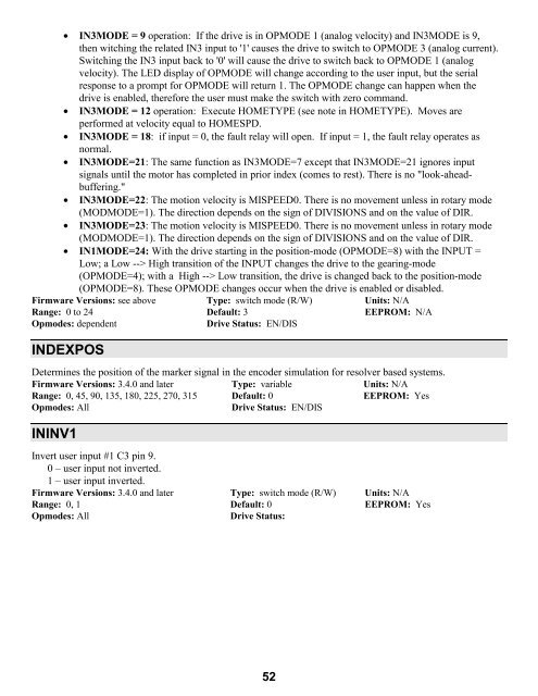
• IN3MODE = 9 operation: If the drive is in OPMODE 1 (analog velocity) <strong>and</strong> IN3MODE is 9,<br />
then witching the related IN3 input to '1' causes the drive to switch to OPMODE 3 (analog current).<br />
Switching the IN3 input back to '0' will cause the drive to switch back to OPMODE 1 (analog<br />
velocity). The LED display of OPMODE will change according to the user input, but the serial<br />
response to a prompt for OPMODE will return 1. The OPMODE change can happen when the<br />
drive is enabled, therefore the user must make the switch with zero comm<strong>and</strong>.<br />
• IN3MODE = 12 operation: Execute HOMETYPE (see note in HOMETYPE). Moves are<br />
performed at velocity equal to HOMESPD.<br />
• IN3MODE = 18: if input = 0, the fault relay will open. If input = 1, the fault relay operates as<br />
normal.<br />
• IN3MODE=21: The same function as IN3MODE=7 except that IN3MODE=21 ignores input<br />
signals until the motor has completed in prior index (comes to rest). There is no "look-aheadbuffering."<br />
• IN3MODE=22: The motion velocity is MISPEED0. There is no movement unless in rotary mode<br />
(MODMODE=1). The direction depends on the sign of DIVISIONS <strong>and</strong> on the value of DIR.<br />
• IN3MODE=23: The motion velocity is MISPEED0. There is no movement unless in rotary mode<br />
(MODMODE=1). The direction depends on the sign of DIVISIONS <strong>and</strong> on the value of DIR.<br />
• IN1MODE=24: With the drive starting in the position-mode (OPMODE=8) with the INPUT =<br />
Low; a Low --> High transition of the INPUT changes the drive to the gearing-mode<br />
(OPMODE=4); with a High --> Low transition, the drive is changed back to the position-mode<br />
(OPMODE=8). These OPMODE changes occur when the drive is enabled or disabled.<br />
Firmware Versions: see above Type: switch mode (R/W) Units: N/A<br />
Range: 0 to 24 Default: 3 EEPROM: N/A<br />
Opmodes: dependent Drive Status: EN/DIS<br />
INDEXPOS<br />
Determines the position of the marker signal in the encoder simulation for resolver based systems.<br />
Firmware Versions: 3.4.0 <strong>and</strong> later Type: variable Units: N/A<br />
Range: 0, 45, 90, 135, 180, 225, 270, 315 Default: 0 EEPROM: Yes<br />
Opmodes: All Drive Status: EN/DIS<br />
ININV1<br />
Invert user input #1 C3 pin 9.<br />
0 – user input not inverted.<br />
1 – user input inverted.<br />
Firmware Versions: 3.4.0 <strong>and</strong> later Type: switch mode (R/W) Units: N/A<br />
Range: 0, 1 Default: 0 EEPROM: Yes<br />
Opmodes: All Drive Status:<br />
52