Setup and Reference Guide - Kollmorgen
Setup and Reference Guide - Kollmorgen
Setup and Reference Guide - Kollmorgen

You also want an ePaper? Increase the reach of your titles
YUMPU automatically turns print PDFs into web optimized ePapers that Google loves.
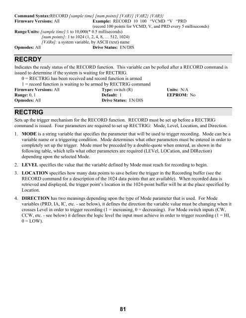
Comm<strong>and</strong> Syntax:RECORD [sample time] [num points] [VAR1] {VAR2} {VAR3}<br />
Firmware Versions: All Example: RECORD 10 100 “VCMD “V “PRD<br />
(record 100 points for VCMD, V, <strong>and</strong> PRD every 5 milliseconds)<br />
Range/Units: [sample time]:1 to 10,000(* 0.5 milliseconds)<br />
[num points]: 1 to 1024 (1, 2, 4, 8, … 512, 1024)<br />
[VARn]: a system variable, by ASCII (text) name<br />
Opmodes: All Drive Status: EN/DIS<br />
RECRDY<br />
Indicates the ready status of the RECORD function. This variable can be polled after a RECORD comm<strong>and</strong> is<br />
issued to determine if the system is waiting for RECTRIG.<br />
0 = RECTRIG has been received <strong>and</strong> record function is armed<br />
1 = record function is waiting to be armed by RECTRIG comm<strong>and</strong><br />
Firmware Versions: All Type: switch (R) Units: N/A<br />
Range: 0, 1 Default: 1 EEPROM: No<br />
Opmodes: All Drive Status: EN/DIS<br />
RECTRIG<br />
Sets up the trigger mechanism for the RECORD function. RECORD must be set up before a RECTRIG<br />
comm<strong>and</strong> is issued. Four parameters are required to set up RECTRIG: Mode, Level, Location, <strong>and</strong> Direction.<br />
1. MODE is a string variable that specifies the parameter that will be used to trigger recording. Mode can be a<br />
variable name or a triggering condition. Mode determines what other parameters must be entered in order to<br />
completely set up the trigger. Mode must be preceded by a double-quote when entered, as shown in the<br />
following table, which tells what other parameters are required (LEVel, LOCation, <strong>and</strong> DIRection)<br />
depending upon the selected Mode.<br />
2. LEVEL specifies the value that the variable defined by Mode must reach for recording to begin.<br />
3. LOCATION specifies how many data points to save before the trigger in the Recording buffer (see the<br />
RECORD comm<strong>and</strong> for a description of the 1024 data points that are available). When recorded data is<br />
retrieved <strong>and</strong> displayed, the trigger point’s location in the 1024-point buffer will be at the place specified by<br />
Location.<br />
4. DIRECTION has two meanings depending upon the type of Mode parameter that is used. For Mode<br />
variables (PRD, IA, IC, etc. - see below), it defines the direction the variable value must be changing when it<br />
crosses Level in order to trigger recording (1 = increasing, 0 = decreasing). For Mode switch inputs (CW,<br />
CCW, etc. - see below) it defines the logic level the input must achieve in order to trigger recording (1 = HI,<br />
0 = LOW).<br />
81