Register your product now - Radiometer Analytical
Register your product now - Radiometer Analytical
Register your product now - Radiometer Analytical

You also want an ePaper? Increase the reach of your titles
YUMPU automatically turns print PDFs into web optimized ePapers that Google loves.
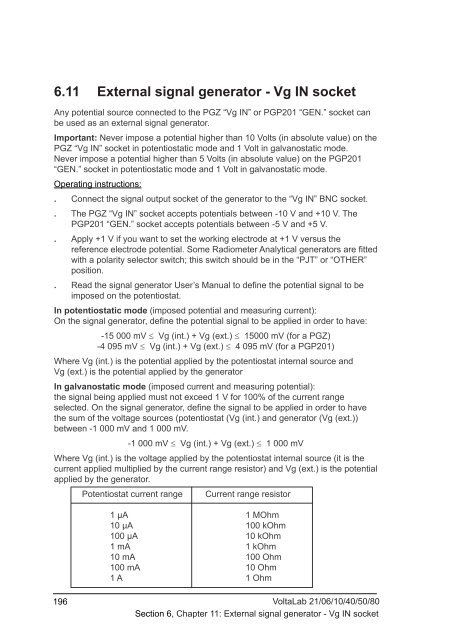
6.11 External signal generator - Vg IN socketAny potential source connected to the PGZ “Vg IN” or PGP201 “GEN.” socket canbe used as an external signal generator.Important: Never impose a potential higher than 10 Volts (in absolute value) on thePGZ “Vg IN” socket in potentiostatic mode and 1 Volt in galvanostatic mode.Never impose a potential higher than 5 Volts (in absolute value) on the PGP201“GEN.” socket in potentiostatic mode and 1 Volt in galvanostatic mode.Operating instructions:. Connect the signal output socket of the generator to the “Vg IN” BNC socket.. The PGZ “Vg IN” socket accepts potentials between -10 V and +10 V. ThePGP201 “GEN.” socket accepts potentials between -5 V and +5 V.. Apply +1 V if you want to set the working electrode at +1 V versus thereference electrode potential. Some <strong>Radiometer</strong> <strong>Analytical</strong> generators are fittedwith a polarity selector switch; this switch should be in the “PJT” or “OTHER”position.. Read the signal generator User’s Manual to define the potential signal to beimposed on the potentiostat.In potentiostatic mode (imposed potential and measuring current):On the signal generator, define the potential signal to be applied in order to have:-15 000 mV ≤ Vg (int.) + Vg (ext.) ≤ 15000 mV (for a PGZ)-4 095 mV ≤ Vg (int.) + Vg (ext.) ≤ 4 095 mV (for a PGP201)Where Vg (int.) is the potential applied by the potentiostat internal source andVg (ext.) is the potential applied by the generatorIn galvanostatic mode (imposed current and measuring potential):the signal being applied must not exceed 1 V for 100% of the current rangeselected. On the signal generator, define the signal to be applied in order to havethe sum of the voltage sources (potentiostat (Vg (int.) and generator (Vg (ext.))between -1 000 mV and 1 000 mV.-1 000 mV ≤ Vg (int.) + Vg (ext.) ≤ 1 000 mVWhere Vg (int.) is the voltage applied by the potentiostat internal source (it is thecurrent applied multiplied by the current range resistor) and Vg (ext.) is the potentialapplied by the generator.Potentiostat current rangeCurrent range resistor1 µA 1 MOhm10 µA 100 kOhm100 µA 10 kOhm1 mA 1 kOhm10 mA 100 Ohm100 mA 10 Ohm1 A 1 Ohm196VoltaLab 21/06/10/40/50/80Section 6, Chapter 11: External signal generator - Vg IN socket