- Page 1 and 2:
Register your product nowTo keep up
- Page 3 and 4:
ContentsRegister your product now 1
- Page 5 and 6:
1. General presentationDear Custome
- Page 7 and 8:
Precautionary LabelsRead all labels
- Page 9:
1.3 VoltaLab 21 Economical Electroc
- Page 12 and 13:
1.6 VoltaLab 40 Dynamic Electrochem
- Page 14:
1.8 VoltaLab 80 Universal Electroch
- Page 20:
Edit the Other settings parameters.
- Page 23 and 24:
2.5 Uninstalling VoltaMaster 4Volta
- Page 25 and 26:
3. Getting startedFor a VoltaLab 10
- Page 28:
For a VoltaLab 06RS232 cable9-pin f
- Page 31 and 32:
3.3 User identificationIf you selec
- Page 33 and 34:
3.5 Set up your instrumentIf you se
- Page 35 and 36:
3.7 Set up the Other settings param
- Page 37 and 38: 4. VoltaMaster 44.1 The VoltaMaster
- Page 39 and 40: Curve type bar - XX is the abscissa
- Page 41: 4.2 Using the VoltaMaster 4 Help fi
- Page 45 and 46: 4.3.1 Open Circuit PotentialThe Ope
- Page 47 and 48: Visual IFVA virtual front panel is
- Page 49 and 50: 4.3.13 Pot. Dynamic EIS (Impedance)
- Page 51 and 52: 4.3.17 Gal. Expert EIS (Impedance)T
- Page 53 and 54: 4.3.22 Pot. Step by step CVStep by
- Page 55 and 56: 4.3.28 Gal. Universal DPThe Gal. Un
- Page 57 and 58: 4.3.34 Pot. Low Current CAA potenti
- Page 59 and 60: 4.3.40 Auto. TrajectThe Auto. Traje
- Page 61 and 62: 4.3.46 Standard calibrationThis met
- Page 63 and 64: 4.3.47 Calibration by additionThis
- Page 65 and 66: 4.3.53 Print ReportThe Print Report
- Page 67 and 68: The following guidances are given i
- Page 69 and 70: 8. Save the sequenceThe initial dat
- Page 71 and 72: 4.5.1 Before starting a sequenceChe
- Page 73 and 74: 4.6 Processing curves to obtain res
- Page 75 and 76: 4.6.1 Post run processing functions
- Page 77 and 78: InformationDisplay information on a
- Page 79 and 80: Evans plotDisplay the Evans diagram
- Page 81 and 82: 4.7 PrintoutsThe Printpreview iconV
- Page 83 and 84: 4.7.3 Preparing a printoutThe “Fi
- Page 85 and 86: 4.7.5 Printing the parameters of an
- Page 87: 4.7.6 Printing CurvesA curve or an
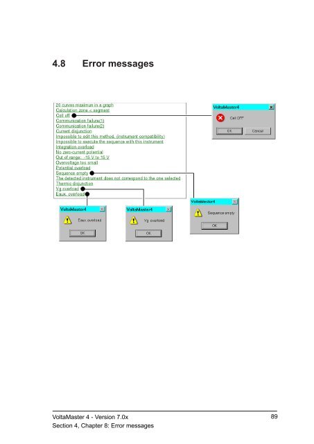
- Page 91 and 92: 4. Communication failure (1)This me
- Page 93 and 94: 7. Impossible to edit this method,
- Page 95 and 96: 14. Sequence emptyYou are trying to
- Page 97 and 98: 18. Eaux overloadThis error message
- Page 99 and 100: 4.9.4 Some windows are not entirely
- Page 101 and 102: The “Static Automatic” compensa
- Page 103 and 104: 4.11 The VoltaMaster 4 files4.11.1
- Page 105 and 106: 4.12 Menus and icons of VoltaMaster
- Page 107 and 108: Menu “Run” (Full and Supervisor
- Page 109 and 110: 4.12.2 From a curve windowMenu “F
- Page 111 and 112: Menu “Curve” (Full and Supervis
- Page 113 and 114: 5. PotentiostatsWarning!These poten
- Page 115 and 116: On/Off switch (1)When the potentios
- Page 117 and 118: The “REF” socket: BNC type coax
- Page 119 and 120: 5.1.3 InstallationWarning!Set up th
- Page 121 and 122: 2. Connecting the computerSee Chapt
- Page 123 and 124: 5.1.5 Troubleshooting1 The pilot la
- Page 125 and 126: 5.1.6 MaintenanceThe PGZ and PST po
- Page 127 and 128: Functional ground- banana socket to
- Page 129 and 130: Other connectionsE OUT (Measured po
- Page 131 and 132: E (X) IN (Channel X)- BNC coaxial s
- Page 133 and 134: PST050 Analytical PotentiostatRegul
- Page 135 and 136: 5.2 The PGP201 Potentiostat - Galva
- Page 137 and 138: “REF”, “AUX” and “WORK”
- Page 139 and 140:
Mains supply section (15)This secti
- Page 141 and 142:
1. Connecting the electrodesConnect
- Page 143 and 144:
5.2.4 UseThe PGP201 potentiostat is
- Page 145 and 146:
8. The PGP201 starts to oscillate c
- Page 147 and 148:
5.2.7 Technical specificationsRegul
- Page 149 and 150:
6. Combination with additionalhardw
- Page 151 and 152:
On the TACHYPROCESSORTurn the “CO
- Page 153 and 154:
6.2 BipotentiostatThe bipotentiosta
- Page 155 and 156:
For more information, see section 3
- Page 157 and 158:
6.3.2 SampleWorking Electrode: Rota
- Page 159 and 160:
1-a) Disc and ringAccording to [1],
- Page 161 and 162:
6.4 Rotating Disc Stand RDS010While
- Page 163 and 164:
6.5 HMDE (MDE150)6.5.1 ConnectionsM
- Page 165 and 166:
Specification of the test : Pb/Cd i
- Page 167 and 168:
Curve examinationThe curves were au
- Page 169 and 170:
Determine the peak and integrate th
- Page 171 and 172:
Concentration resultStandard additi
- Page 173 and 174:
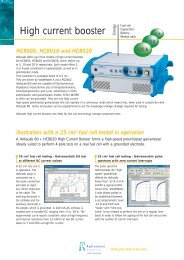
6.7 HVB100 High Voltage BoosterThe
- Page 175 and 176:
Cables 1 to 3 are supplied in the C
- Page 177 and 178:
6.7.5 Set up the other settingsSet
- Page 179 and 180:
6.7.9 CE MarkingThe HVB100 High Vol
- Page 181 and 182:
6.8.1 ConnectionsWarning!Set up the
- Page 183 and 184:
Click the “Test” button. The in
- Page 185 and 186:
6.8.4 Set up your cellIf you run a
- Page 187 and 188:
6.8.8 Technical specifications - HC
- Page 189 and 190:
6.8.9 CE MarkingThe HCB005, HCB010
- Page 191 and 192:
6.10 AMU130 - PGZ402 E(X) IN and I(
- Page 193 and 194:
Declare the AMU130 as a “Potentio
- Page 195 and 196:
6.10.5 Set up the other settingsSel
- Page 197 and 198:
Example : with the 10 µA current r
- Page 199:
. While editing the sequence, selec