

VGB POWERTECH 7 (2020) - International Journal for Generation and Storage of Electricity and Heat
VGB PowerTech - International Journal for Generation and Storage of Electricity and Heat. Issue 7 (2020). Technical Journal of the VGB PowerTech Association. Energy is us! Maintenance. Thermal waste utilisation
VGB PowerTech - International Journal for Generation and Storage of Electricity and Heat. Issue 7 (2020).
Technical Journal of the VGB PowerTech Association. Energy is us!
Maintenance. Thermal waste utilisation

You also want an ePaper? Increase the reach of your titles
YUMPU automatically turns print PDFs into web optimized ePapers that Google loves.
<strong>VGB</strong> PowerTech 7 l <strong>2020</strong><br />
Refractory linings under thermomechanical aspects<br />
n S [MN/m]: Circumferential tensile <strong>for</strong>ce<br />
in steel casing<br />
In order to obtain the actual radial displacement<br />
u W , compatibilities <strong>of</strong> the layer<br />
displacements with each other must be defined;<br />
since there is continuity at the layer<br />
boundaries, i.e. layers are not penetrated<br />
by other layers, the actual “compatible”<br />
displacements can only occur under constraint<br />
<strong>for</strong>ces in equilibrium.<br />
In this example this displacement compatibility<br />
is defined as follows:<br />
u s = u W + Σ(∆t k ) (17)<br />
u s [m]: Actual radial displacement <strong>of</strong><br />
the steel casing to the outside<br />
u W [m]: Actual radial displacement <strong>of</strong><br />
the wear layer to the outside<br />
Σ(∆t k )[m]: Sum <strong>of</strong> the layer thickness<br />
changes <strong>of</strong> the solely radially<br />
pressed insulating layers<br />
u S = u 0,S + u R,S = (ε 0,S + ε R,S ) * R S (18)<br />
u W = u 0,W + u r,W = (ε 0,W + ε R,W ) * R W (19)<br />
Σ(∆t k ) = Σ[(ε 0,tk + ε R,tk ) * t k ] (20)<br />
(R S , R W : Average radius <strong>of</strong> the steel casing<br />
or the wear layer, t k : Thickness <strong>of</strong> the respective<br />
insulation layers, k = 1, 2, …)<br />
Inserting (7) in (18), (19) <strong>and</strong> (20) in compliance<br />
with a uni<strong>for</strong>m sign definition <strong>for</strong><br />
the radial displacements allows to dissolve<br />
after the compressive <strong>for</strong>ce in the wear<br />
layer, the tensile <strong>for</strong>ce in the steel casing or<br />
the radial compression in the insulation<br />
layers (Figure 2).<br />
The assumption <strong>of</strong> mean normal <strong>for</strong>ces<br />
(“rod analogy”) naturally represents a simplification<br />
compared to the real conditions;<br />
however, if the diameter <strong>of</strong> the construction<br />
is much larger than the layer thicknesses,<br />
this approach according to the<br />
“spring-in-line principle” provides very<br />
good approximate results in many lining<br />
cases by capturing the relevant parameters<br />
<strong>of</strong> all components.<br />
Conclusions<br />
The described correlations <strong>of</strong> thermomechanically<br />
induced constraint underline<br />
the dependence <strong>of</strong> the <strong>for</strong>ce variables on<br />
the stiffness <strong>of</strong> all components <strong>of</strong> a layered<br />
structure. The choice <strong>of</strong> layer thicknesses,<br />
anchor cross-sections <strong>and</strong> materials there<strong>for</strong>e<br />
represents a criterion <strong>for</strong> limiting<br />
stresses beyond the usual chemical <strong>and</strong><br />
thermal requirements.<br />
Equilibrium <strong>of</strong> <strong>for</strong>ces<br />
Displacement compatibility<br />
Layer n properties<br />
Layer temperature<br />
T n<br />
(n: wear layer, insulation layers, steel) Coefficient <strong>of</strong> thermal expansion α T,n<br />
— —<br />
Layer thickness<br />
t n<br />
Secant/Elasticity modulus E n<br />
σ<br />
Stress-strain relationship<br />
RW<br />
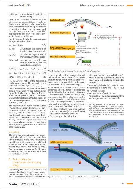
Considering the above, it is clear that the<br />
shape <strong>and</strong> design <strong>of</strong> the structure – curvature<br />
dimensions, layer thicknesses, etc. –<br />
are <strong>of</strong> elementary importance <strong>for</strong> the determination<br />
<strong>of</strong> the <strong>for</strong>ce magnitudes <strong>and</strong><br />
de<strong>for</strong>mations. In the course <strong>of</strong> thermomechanical<br />
design, the “potentials” <strong>of</strong> all components<br />
are to be identified in order to determine<br />
their influences realistically.<br />
As an example, a system section, which<br />
comprises different zones <strong>of</strong> a circulating<br />
fluidized bed facility – cylindrical parts <strong>of</strong><br />
the fluidized bed chamber <strong>and</strong> the cyclone,<br />
the connecting flat-walled duct <strong>and</strong> a<br />
strongly inwardly curved bullnose – is considered.<br />
The lining is assumed to be consistent<br />
over all areas with the following characteristic<br />
properties (see F i g u r e 3 a ):<br />
––<br />
Stiff back-anchored wear layer material<br />
without expansion joints or with joints<br />
that are closed during operation<br />
––<br />
Steel casing rein<strong>for</strong>ced by ribs<br />
p<br />
Free displacements u 0,S , u 0,W<br />
Forced displacements, resettings u R,S , u R,W<br />
Actual displacements u S , u W<br />
R W<br />
E sec = σ/ε<br />
ε = u R /R<br />
Fig. 2. Mechanical principles <strong>for</strong> the structural elements’ interaction.<br />
FLUID BED CHAMBER<br />
a) Characteristic zones<br />
DUCT<br />
n S = n W = p * R W<br />
––<br />
One-piece anchors fixed on both sides*<br />
––<br />
Only thermally relevant intermediate<br />
layer (very s<strong>of</strong>t insulation compared to<br />
anchors)*<br />
The resulting behavioral characteristics can<br />
be described as follows (see F i g u r e 3 b ):<br />
(a) Cylindrical areas<br />
––<br />
Outward urge <strong>of</strong> the front layer<br />
––<br />
“Compatible” radial displacement <strong>of</strong> the<br />
entire layer structure to the outside<br />
* Here it is assumed that only the anchors transmit<br />
radial compression. This is due to their<br />
high stiffness in comparison to the insulation<br />
<strong>and</strong> their own tendency to exp<strong>and</strong> (high α T ).<br />
Using the insulation layer as an essential loadbearing<br />
element instead would lead to unrealistic<br />
results!<br />
BULLNOSE<br />
CYCLONE<br />
3. Typical behaviour<br />
characteristics <strong>of</strong> refractory<br />
linings<br />
b) Force flows within the lining<br />
Fig. 3. Different zones result in different behavioural characteristics.<br />
47


