

VGB POWERTECH 7 (2020) - International Journal for Generation and Storage of Electricity and Heat
VGB PowerTech - International Journal for Generation and Storage of Electricity and Heat. Issue 7 (2020). Technical Journal of the VGB PowerTech Association. Energy is us! Maintenance. Thermal waste utilisation
VGB PowerTech - International Journal for Generation and Storage of Electricity and Heat. Issue 7 (2020).
Technical Journal of the VGB PowerTech Association. Energy is us!
Maintenance. Thermal waste utilisation

You also want an ePaper? Increase the reach of your titles
YUMPU automatically turns print PDFs into web optimized ePapers that Google loves.
Tensile stress anchor [MPa]<br />
<strong>VGB</strong> PowerTech 7 l <strong>2020</strong><br />
Refractory linings under thermomechanical aspects<br />
h<br />
P R<br />
L S<br />
Open joint<br />
δ T,C<br />
δ R<br />
"Free" deflection <strong>of</strong> the concrete slab due<br />
to temperature gradient<br />
Reset deflection <strong>of</strong> the concrete slab due<br />
to bulging obstruction by anchors<br />
Reset anchor <strong>for</strong>ce<br />
Maximum bending stress in concrete<br />
only the anchors are capable <strong>of</strong> withst<strong>and</strong>ing<br />
tension normal to the panel.<br />
From the data <strong>for</strong> height, width <strong>and</strong> thickness<br />
<strong>of</strong> the panel strip, the anchor length<br />
<strong>and</strong> its cross-section as well as the material<br />
stiffnesses, the resetting <strong>for</strong>ce <strong>of</strong> the central<br />
anchor can be determined <strong>and</strong> from<br />
this, in turn, the bending stress in the concrete<br />
panel can be derived.<br />
Against the background that these constraint<br />
stresses can be many times the<br />
stresses due to dead load, it is tempting to<br />
ensure the load-bearing capacity by increasing<br />
the anchor cross-sections. This<br />
can prove to be counterproductive in that it<br />
results in the <strong>of</strong>ten observed through<br />
cracking <strong>of</strong> the concrete slabs. While the<br />
tensile stress in the anchor hardly drops,<br />
the bending stress in the concrete rises<br />
drastically. To the same extent as the resistance<br />
<strong>of</strong> the anchor increases, the constraint<br />
under which the concrete “suffers” increases<br />
due to the higher anchor stiffness (F i g -<br />
ure 12).<br />
d c<br />
α T,C ΔT G<br />
Fig. 11. Computation principle <strong>for</strong> determining anchor <strong>for</strong>ces <strong>and</strong> layer stresses.<br />
During cooling, the negative gradient<br />
reaches its highest value, the free concave<br />
curvature <strong>of</strong> the panel is hindered by “external<br />
constraint”, i.e. the central anchors<br />
are compressed the most <strong>and</strong> the external<br />
anchors are pulled the most. Accordingly,<br />
the negative bending moment also reaches<br />
its maximum.**<br />
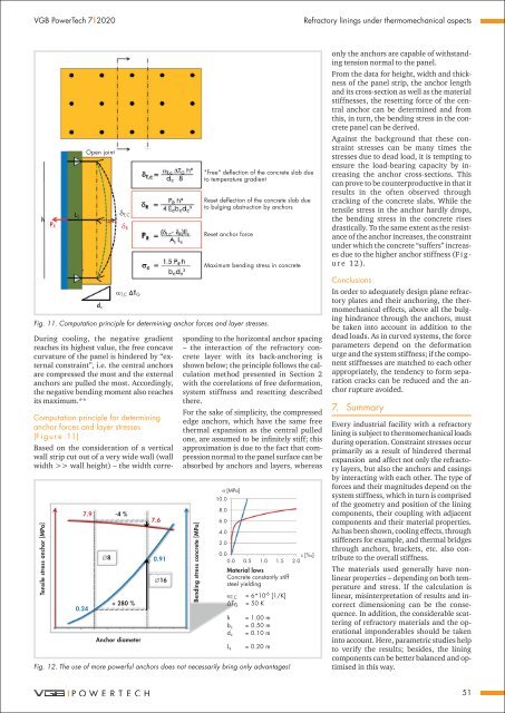
7.9<br />
0.24<br />
∅8<br />
-4 %<br />
+ 280 %<br />
Anchor diameter<br />
7.6<br />
0.91<br />
∅16<br />
Computation principle <strong>for</strong> determining<br />
anchor <strong>for</strong>ces <strong>and</strong> layer stresses<br />
(F i g u r e 11)<br />
Based on the consideration <strong>of</strong> a vertical<br />
wall strip cut out <strong>of</strong> a very wide wall (wall<br />
width >> wall height) – the width corresponding<br />
to the horizontal anchor spacing<br />
– the interaction <strong>of</strong> the refractory concrete<br />
layer with its back-anchoring is<br />
shown below; the principle follows the calculation<br />
method presented in Section 2<br />
with the correlations <strong>of</strong> free de<strong>for</strong>mation,<br />
system stiffness <strong>and</strong> resetting described<br />
there.<br />
For the sake <strong>of</strong> simplicity, the compressed<br />
edge anchors, which have the same free<br />
thermal expansion as the central pulled<br />
one, are assumed to be infinitely stiff; this<br />
approximation is due to the fact that compression<br />
normal to the panel surface can be<br />
absorbed by anchors <strong>and</strong> layers, whereas<br />
Bending stress concrete [MPa]<br />
σ [MPa]<br />
10.0<br />
8.0<br />
6.0<br />
4.0<br />
2.0<br />
0.0<br />
ε [‰]<br />
0.0 0.5 1.0 1.5 2.0<br />
Material laws<br />
Concrete constantly stiff<br />
steel yielding<br />
α T,C = 6*10 -6 [1/K]<br />
ΔT G = 50 K<br />
h<br />
b c<br />
d c<br />
L s<br />
= 1.00 m<br />
= 0.50 m<br />
= 0.10 m<br />
= 0.20 m<br />
Fig. 12. The use <strong>of</strong> more powerful anchors does not necessarily bring only advantages!<br />
Conclusions<br />
In order to adequately design plane refractory<br />
plates <strong>and</strong> their anchoring, the thermomechanical<br />
effects, above all the bulging<br />
hindrance through the anchors, must<br />
be taken into account in addition to the<br />
dead loads. As in curved systems, the <strong>for</strong>ce<br />
parameters depend on the de<strong>for</strong>mation<br />
urge <strong>and</strong> the system stiffness; if the component<br />
stiffnesses are matched to each other<br />
appropriately, the tendency to <strong>for</strong>m separation<br />
cracks can be reduced <strong>and</strong> the anchor<br />
rupture avoided.<br />
7. Summar y<br />
Every industrial facility with a refractory<br />
lining is subject to thermomechanical loads<br />
during operation. Constraint stresses occur<br />
primarily as a result <strong>of</strong> hindered thermal<br />
expansion <strong>and</strong> affect not only the refractory<br />
layers, but also the anchors <strong>and</strong> casings<br />
by interacting with each other. The type <strong>of</strong><br />
<strong>for</strong>ces <strong>and</strong> their magnitudes depend on the<br />
system stiffness, which in turn is comprised<br />
<strong>of</strong> the geometry <strong>and</strong> position <strong>of</strong> the lining<br />
components, their coupling with adjacent<br />
components <strong>and</strong> their material properties.<br />
As has been shown, cooling effects, through<br />
stiffeners <strong>for</strong> example, <strong>and</strong> thermal bridges<br />
through anchors, brackets, etc. also contribute<br />
to the overall stiffness.<br />
The materials used generally have nonlinear<br />
properties – depending on both temperature<br />
<strong>and</strong> stress. If the calculation is<br />
linear, misinterpretation <strong>of</strong> results <strong>and</strong> incorrect<br />
dimensioning can be the consequence.<br />
In addition, the considerable scattering<br />
<strong>of</strong> refractory materials <strong>and</strong> the operational<br />
imponderables should be taken<br />
into account. Here, parametric studies help<br />
to verify the results; besides, the lining<br />
components can be better balanced <strong>and</strong> optimised<br />
in this way.<br />
51


