1. First steps in Reaktor Core - Native Instruments
1. First steps in Reaktor Core - Native Instruments
1. First steps in Reaktor Core - Native Instruments

Create successful ePaper yourself
Turn your PDF publications into a flip-book with our unique Google optimized e-Paper software.
6.28319 is 2*π, which is then divided by the sampl<strong>in</strong>g rate, form<strong>in</strong>g the value<br />
to be multiplied with the cutoff frequency. We don’t need a modulation multiplier,<br />
because F logically is a control signal <strong>in</strong>put, so we might perform the<br />
<strong>in</strong>itial multiplication even if there is no <strong>in</strong>itialization event at the F <strong>in</strong>put.<br />
We perform the division before the multiplication, because the division<br />
is relatively heavy on the CPU, and the sampl<strong>in</strong>g rate doesn’t change<br />
that often. If only the cutoff frequency changes, there are no events<br />
sent to the divisor module, and therefore, the division will not be performed.<br />
This is one of the standard optimizations that can be done by<br />
the core-structure designer.<br />
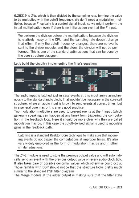
Let’s build the circuitry implement<strong>in</strong>g the filter’s equation:<br />
The audio <strong>in</strong>put is latched just <strong>in</strong> case events at this <strong>in</strong>put arrive asynchronously<br />
to the standard audio clock. That wouldn’t be necessary <strong>in</strong> the core-cell<br />
structure, where an audio <strong>in</strong>put is known to send events at correct times, but<br />
<strong>in</strong> a general core macro it is a very good practice.<br />
Two modulation multipliers are used to prevent events at the F <strong>in</strong>put (which<br />
generally speak<strong>in</strong>g, can happen at any time) from trigger<strong>in</strong>g the computation<br />
<strong>in</strong> the feedback loop. Here it should be more clear why they are called<br />
modulation macros, <strong>in</strong> this case the cutoff-derived signal is used to modulate<br />
ga<strong>in</strong>s <strong>in</strong> the feedback path.<br />
Latch<strong>in</strong>g is a standard <strong>Reaktor</strong> <strong>Core</strong> technique to make sure that <strong>in</strong>com<strong>in</strong>g<br />
events do not trigger the computations at improper times. It’s also<br />
very widely employed <strong>in</strong> the form of modulation macros and <strong>in</strong> other<br />
similar situations.<br />
The Z^-1 module is used to store the previous output value and will automatically<br />
send an event with the previous output value on every audio clock tick.<br />
It also takes care of possible denormal values which otherwise could occur.<br />
Those familiar with DSP should notice that the structure looks pretty much<br />
similar to the standard DSP filter diagrams.<br />
The Merge module at the adder output is mak<strong>in</strong>g sure that the filter state<br />
REAKTOR CORE – 103