- Page 1 and 2:
REAKTOR CORE Tutorial
- Page 3 and 4:
Table of Contents 1. First steps in
- Page 5 and 6:
Appendix D. Core cell ports .......
- Page 7 and 8:
H.7. Audio Mix-Amp > Gain (dB) ....
- Page 9 and 10:
H.88. Logic > GT / IGT ............
- Page 11 and 12:
1. First steps in Reaktor Core 1.1.
- Page 13 and 14:
You may also want to save core cell
- Page 15 and 16:
1.3. Using core cells in a real exa
- Page 17 and 18:
1.4. Basic editing of core cells No
- Page 19 and 20:
You can shrink them back by right-c
- Page 21 and 22:
or design of the module. Generally,
- Page 23 and 24:
And here is an example of an event
- Page 25 and 26:
converter. As a result, our control
- Page 27 and 28:
The VCF section could be promising,
- Page 29 and 30:
There’s only one kind of module y
- Page 31 and 32:
As the name implies (and the info t
- Page 33 and 34:
Now you can type some text into the
- Page 35 and 36:
Instead of a nasty looking diagonal
- Page 37 and 38:
Some types of processing, mixing fo
- Page 39 and 40:
mix it with the delayed signal. Bec
- Page 41 and 42:
0.02ms at 44.1kHz, even less at hig
- Page 43 and 44:
The Latch and Bool C types of ports
- Page 45 and 46:
In the value field type a new value
- Page 47 and 48:
modules in the same way we did earl
- Page 49 and 50:
2.5. Using audio as control signal
- Page 51 and 52:
some primary-level event signals us
- Page 53 and 54:
is always at full amplitude. At 1 t
- Page 55 and 56:
The Gate2L, AND, and L2Gate modules
- Page 57 and 58:
Here is a picture of a continuous s
- Page 59 and 60:
3.3. Simultaneous events Consider t
- Page 61 and 62:
3.4. Processing order As you have s
- Page 63 and 64:
Event Inputs send core events to th
- Page 65 and 66:
Of course, in this particular case
- Page 67 and 68:
Now move the knob and watch the out
- Page 69 and 70:
4.2. Object Bus Connections Object
- Page 71 and 72:
As mentioned, the above structure i
- Page 73 and 74:
constants would send their values a
- Page 75 and 76:
4.4. Building an event accumulator
- Page 77 and 78:
� �� �� �� ���
- Page 79 and 80:
Now the reset works as specified. T
- Page 81 and 82:
output values. Let’s try that wit
- Page 83 and 84:
Should any files be found in this C
- Page 85 and 86:
The name “Modulation”, although
- Page 87 and 88:
5. Audio processing at its core 5.1
- Page 89 and 90:
5.2. Sampling rate clock bus A coup
- Page 91 and 92:
We have already seen a structure bu
- Page 93 and 94:
connections will be marked as inval
- Page 95 and 96:
As you can see, the clock input of
- Page 97 and 98:
left which we cannot see from the o
- Page 99 and 100:
samples, we have to produce several
- Page 101 and 102:
5.6. Other bad numbers Denormal num
- Page 103 and 104:
6.28319 is 2*π, which is then divi
- Page 105 and 106:
6. Conditional processing 6.1. Even
- Page 107 and 108:
In this version, the 0 output of th
- Page 109 and 110:
First we are going to build the cir
- Page 111 and 112:
default means use whatever precisio
- Page 113 and 114:
Switching between float and integer
- Page 115 and 116:
The output and all built-in modules
- Page 117 and 118:
The OBC chain at the bottom keeps t
- Page 119 and 120:
The speed of the number change in t
- Page 121 and 122:
And now the connection: The upper i
- Page 123 and 124:
This macro internally has an Index
- Page 125 and 126:
The four Write [] modules will take
- Page 127 and 128:
In general, you should also take ca
- Page 129 and 130:
� ������� ���
- Page 131 and 132:
The size property of the array can
- Page 133 and 134:
So we include another macro for wra
- Page 135 and 136:
A new dialog will appear: What you
- Page 137 and 138:
Formal output precision Now that we
- Page 139 and 140: 9. Building optimal structures As a
- Page 141 and 142: 9.3. Numerical operations Floating
- Page 143 and 144: Appendix A. Reaktor Core user inter
- Page 145 and 146: Appendix B. Reaktor Core concept B.
- Page 147 and 148: Appendix C. Core macro ports C.1. I
- Page 149 and 150: Appendix D. Core cell ports D.1. In
- Page 151 and 152: F.3. Math > - Produces the differen
- Page 153 and 154: F.12. Bit > Bit OR Performs the bit
- Page 155 and 156: that the module on the picture abov
- Page 157 and 158: connected to the sidechain input. T
- Page 159 and 160: Appendix G. Expert macros G.1. Clip
- Page 161 and 162: G.12. Math > sqrt Square root appro
- Page 163 and 164: G.24. Memory > Read [] Reads a valu
- Page 165 and 166: Appendix H. Standard macros H.1. Au
- Page 167 and 168: H.8. Audio Mix-Amp > Invert Inverts
- Page 169 and 170: H.15. Audio Mix-Amp > XFade (lin) A
- Page 171 and 172: H.22. Audio Shaper > Sine Shaper 4
- Page 173 and 174: H.30. Control > Ctl Pan “Pans”
- Page 175 and 176: H.38. Convert > ms2sec Converts the
- Page 177 and 178: to positive. The allowed RM values
- Page 179 and 180: H.53. EQ > Static Filter > 1-pole s
- Page 181 and 182: H.62. EQ > Static Filter > 2-pole s
- Page 183 and 184: H.70. Event Processing > Ctl2Gate C
- Page 185 and 186: H.79. LFO > Random LFO Generates a
- Page 187 and 188: H.88. Logic > GT / IGT Compares the
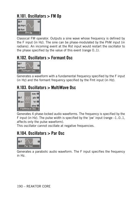
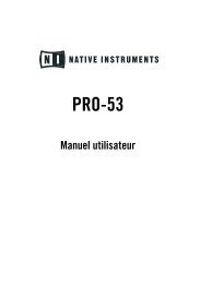
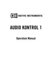
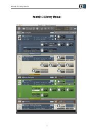
- Page 189: Generates 4 phase-locked audio wave
- Page 193 and 194: H.112. VCF > Diode Ladder Diode-lad
- Page 195 and 196: I.4. Audio Shaper > Parabol Sat Sim
- Page 197 and 198: I.10. Control > Par Ctl Shaper Appl
- Page 199 and 200: I.17. EQ > HighShelf EQ 1-pole high
- Page 201 and 202: I.25. EQ > Static Filter > 2-pole s
- Page 203 and 204: I.33. Oscillator > 4-Wave Mst Gener
- Page 205 and 206: I.39. Oscillator > MultiWave Osc Ge
- Page 207 and 208: I.44. VCF > 2 Pole SV x3 S 2-pole s
- Page 209 and 210: Index A Array module ..............