1. First steps in Reaktor Core - Native Instruments
1. First steps in Reaktor Core - Native Instruments
1. First steps in Reaktor Core - Native Instruments

Create successful ePaper yourself
Turn your PDF publications into a flip-book with our unique Google optimized e-Paper software.
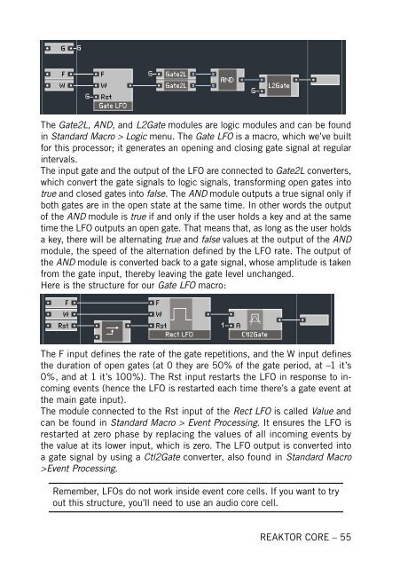
The Gate2L, AND, and L2Gate modules are logic modules and can be found<br />
<strong>in</strong> Standard Macro > Logic menu. The Gate LFO is a macro, which we’ve built<br />
for this processor; it generates an open<strong>in</strong>g and clos<strong>in</strong>g gate signal at regular<br />
<strong>in</strong>tervals.<br />
The <strong>in</strong>put gate and the output of the LFO are connected to Gate2L converters,<br />
which convert the gate signals to logic signals, transform<strong>in</strong>g open gates <strong>in</strong>to<br />
true and closed gates <strong>in</strong>to false. The AND module outputs a true signal only if<br />
both gates are <strong>in</strong> the open state at the same time. In other words the output<br />
of the AND module is true if and only if the user holds a key and at the same<br />
time the LFO outputs an open gate. That means that, as long as the user holds<br />
a key, there will be alternat<strong>in</strong>g true and false values at the output of the AND<br />
module, the speed of the alternation def<strong>in</strong>ed by the LFO rate. The output of<br />
the AND module is converted back to a gate signal, whose amplitude is taken<br />
from the gate <strong>in</strong>put, thereby leav<strong>in</strong>g the gate level unchanged.<br />
Here is the structure for our Gate LFO macro:<br />
The F <strong>in</strong>put def<strong>in</strong>es the rate of the gate repetitions, and the W <strong>in</strong>put def<strong>in</strong>es<br />
the duration of open gates (at 0 they are 50% of the gate period, at –1 it’s<br />
0%, and at 1 it’s 100%). The Rst <strong>in</strong>put restarts the LFO <strong>in</strong> response to <strong>in</strong>com<strong>in</strong>g<br />
events (hence the LFO is restarted each time there’s a gate event at<br />
the ma<strong>in</strong> gate <strong>in</strong>put).<br />
The module connected to the Rst <strong>in</strong>put of the Rect LFO is called Value and<br />
can be found <strong>in</strong> Standard Macro > Event Process<strong>in</strong>g. It ensures the LFO is<br />
restarted at zero phase by replac<strong>in</strong>g the values of all <strong>in</strong>com<strong>in</strong>g events by<br />
the value at its lower <strong>in</strong>put, which is zero. The LFO output is converted <strong>in</strong>to<br />
a gate signal by us<strong>in</strong>g a Ctl2Gate converter, also found <strong>in</strong> Standard Macro<br />
>Event Process<strong>in</strong>g.<br />
Remember, LFOs do not work <strong>in</strong>side event core cells. If you want to try<br />
out this structure, you’ll need to use an audio core cell.<br />
REAKTOR CORE – 55