1. First steps in Reaktor Core - Native Instruments
1. First steps in Reaktor Core - Native Instruments
1. First steps in Reaktor Core - Native Instruments

Create successful ePaper yourself
Turn your PDF publications into a flip-book with our unique Google optimized e-Paper software.
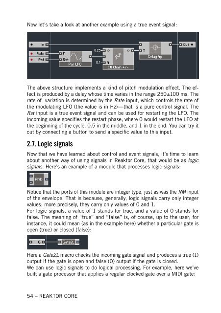
Now let’s take a look at another example us<strong>in</strong>g a true event signal:<br />
The above structure implements a k<strong>in</strong>d of pitch modulation effect. The effect<br />
is produced by a delay whose time varies <strong>in</strong> the range 250±100 ms. The<br />
rate of variation is determ<strong>in</strong>ed by the Rate <strong>in</strong>put, which controls the rate of<br />
the modulat<strong>in</strong>g LFO (the value is <strong>in</strong> Hz)—that is a pure control signal. The<br />
Rst <strong>in</strong>put is a true event signal and can be used for restart<strong>in</strong>g the LFO. The<br />
<strong>in</strong>com<strong>in</strong>g value specifies the restart phase, where 0 would restart the LFO at<br />
the beg<strong>in</strong>n<strong>in</strong>g of the cycle, 0.5 <strong>in</strong> the middle, and 1 <strong>in</strong> the end. You can try it<br />
out by connect<strong>in</strong>g a button to send a specific value to this <strong>in</strong>put.<br />
2.7. Logic signals<br />
Now that we have learned about control and event signals, it’s time to learn<br />
about another way of us<strong>in</strong>g signals <strong>in</strong> <strong>Reaktor</strong> <strong>Core</strong>, that would be as logic<br />
signals. Here’s an example of a module that processes logic signals:<br />
Notice that the ports of this module are <strong>in</strong>teger type, just as was the RM <strong>in</strong>put<br />
of the envelope. That is because, generally, logic signals carry only <strong>in</strong>teger<br />
values; more precisely, they carry only values of 0 and <strong>1.</strong><br />
For logic signals, a value of 1 stands for true, and a value of 0 stands for<br />
false. The mean<strong>in</strong>g of “true” and “false” is, of course, up to the user; for<br />
<strong>in</strong>stance, it could mean (as <strong>in</strong> the example here) whether a particular gate is<br />
open (true) or closed (false):<br />
Here a Gate2L macro checks the <strong>in</strong>com<strong>in</strong>g gate signal and produces a true (1)<br />
output if the gate is open and false (0) output if the gate is closed.<br />
We can use logic signals to do logical process<strong>in</strong>g. For example, here we’ve<br />
built a gate processor that applies a regular clocked gate over a MIDI gate:<br />
54 – REAKTOR CORE